Design of a Qaudruple-arm UHF Dipole Antenna Fed by a Collinear Coaxial Cable
Abstract
In this paper, a design is presented for a quadruple-arm H-shaped UHF dipole antenna fed by a collinear coaxial cable. The dipole antenna is of printed type and has two upper arms on one side of a printed circuit board (PCB) and two lower arms on the other side. Upper and lower arms are fed by a parallel strip line, which is in turn fed by a collinear coaxial cable through an optimally designed transition. Due to the H-shaped geometry of the dipole, the effect of the coaxial cable on the dipole's gain pattern is small. A parametric analysis carried out, based on which an optimum design is obtained for a UHF quadruple-arm dipole antenna. The designed dipole antenna has reflection coefficient of less than -10 dB at 885-1050 MHz, maximum gain of 2.6 dBi at 915 MHz, E-plane gain difference of less than 2.9 dB from that of a half-wave wire dipole antenna, and gain difference of 0.3 dB in the H-plane.
초록
본 논문에서는 동일직선 동축선에 의해 급전되는 4-지선 H-형 UHF 대역 다이폴의 설계를 제시하였다. 다이폴 안테나는 인쇄형이며 인쇄회로기판 (PCB)의 한 면에 있는 2개의 상부 지선과 다른 면에 있는 2개의 하부 지선을 가진다. 상부 및 하부 지선은 평행 스트립 전송선으로 급전되며 이는 다시 최적 설계된 변환부를 통하여 동일직선 동축선에 의해 급전된다. 다이폴의 H 모양의 형상으로 인해 동축선이 다이폴의 이득패턴에 미치는 영향은 작다. 패러미터 분석을 수행하고 이로부터 UHF 대역 4-지선 다이폴 안테나의 최적 설계를 얻었다. 설계된 다이폴 안테나는 885-1050 MHz에서 -10 dB 이하의 반사계수, 915 MHz에서 2.6 dBi의 최대이득, 전계면에서 반파장 도선 다이폴의 이득패턴과 2.9 dB 이하의 차이, 자계면에서 0.3 dB 이하의 이득 차이를 가진다.
Keywords:
dipole antenna, parameter study, quadruple arm, coaxial feeding, coaxial to parallel strip transitionI. Introduction
The simply shaped dipole antenna is used in such applications as antenna gain measurements [1], RFID [2], radio communications [3] and array radars [4], [5]. The basic shape of a dipole antenna can be either cylindrical or planar. Various geometries of the dipole antenna have been devised for broadband [6] and multiband [7] applications.
The H-shaped quadruple-arm dipole element finds applications in base station antennas [8] and collinear arrays [9] due to its relatively wide bandwidth and ease of the feeding. For base station applications, the H-shaped dipole operates above a ground plane over a wide frequency range, while the one for collinear array applications is realized in printed form typically with narrow-band characteristics. The H-shaped dipole with length of one wavelength or more and spacing of one half of the element length is called the lazy-H antenna, which is used as a single antenna or as an element in HF and VHF curtain arrays.
The arms of a printed H-shaped dipole can be on the same surface [9] or on different surfaces [10], [11] with corresponding feeding methods. Existing works on the design of the H-shaped quadruple-arm dipole antenna are rather limited. Yu and co-workers [11] have investigated a double-sided printed quadruplearm dipole element, but their paper does not provide any detailed information on the design. Zhang and co-workers proposed a H-shaped dipole with its arms enclosed in a metallic cylinder for improved omnidirectional gain pattern [12]. Zhang and co-workers presented a single-sided H-shaded dipole fed by slot coupling for wideband operation [13].
In this paper, we present a detailed parametric study and an optimum design of a simple double-sided H-shaped quadruple-arm dipole antenna element and a coaxial to parallel strip line transition for feeding the dipole with a coaxial cable. The performance of the designed dipole fed by a coaxial cable is presented. CST Studio Suite 2019 has been used in the simulation.
Ⅱ. Antenna Design
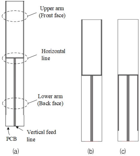
The structure of the dipole antenna designed in the paper is shown in Fig. 1. Upper and lower dual arms of the dipole are fed by a horizontal parallel strip line which in turn is fed by a vertical parallel strip line. Fig. 1(b) and 1(c) show the antenna circuit patterns on the front and back surfaces of the printed circuit board (PCB). Four dipole arms have the same length and width.
Fig. 2 shows dimensional parameters of the proposed antenna. The substrate is Rogers RO4000C with dielectric thickness of 0.813 mm, conductor thickness of 0.034 mm, dielectric constant of 3.55, and loss tangent of 0.0021. The length of the dipole arms determines the operating frequency while other parameters influence antenna impedance matching. A transition between coaxial cable to parallel strip line is added in the later stage of the design.
The dimensions shown in Fig. 2 are adjusted for good impedance matching at 855-975 MHz (120 MHz bandwidth) based on parametric analysis. Table 1 shows the dimensions of the designed antenna.
Four dipole arms have the same length L1. The width W0 of the vertical feed line is set to 2.4 mm for 50-ohm characteristic impedance. Figs. 3 to 6 show the reflection coefficient of the antenna versus various dimensional parameters.
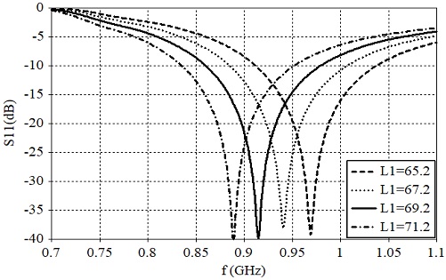
Fig. 3 shows the effect of the dipole arm length L1 on the reflection coefficient. As expected the dipole arm length determines the antenna's operating frequency.
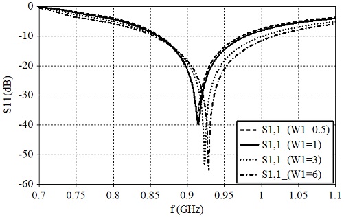
Fig. 4 shows the reflection coefficient versus the dipole arm strip width W1. Wide strip widths result in higher operating frequencies and larger bandwidths. This is contrary to the case of wire dipoles where larger diameters result in lower operating frequencies.
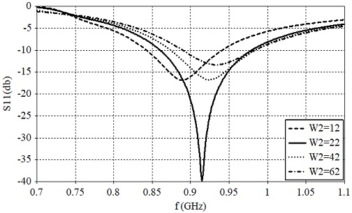
Fig. 5 shows the reflection coefficient versus the distance W2 between dipole arms, where one can observe a good impedance matching can be obtained by proper choice of W2. With other dimensions fixed, W2 can be adjusted to minimize the reflection coefficient at the center frequency.
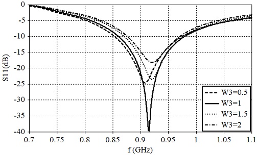
Fig. 6 shows the effect of the width W3 of the horizontal parallel strip feed line on the reflection coefficient. The different values of W3 result in different characteristic impedances of the horizontal feed line so that W3 can be used as a parameter for impedance matching along with W2.
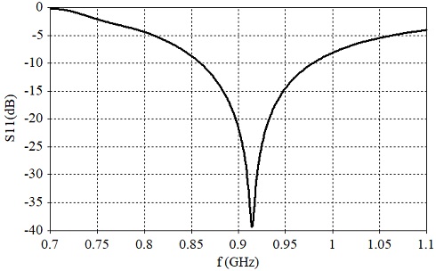
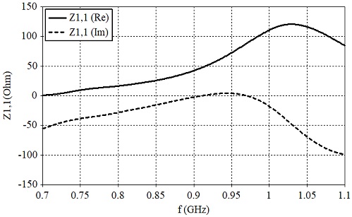
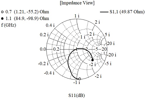
Fig. 7 shows the reflection coefficient of the dipole antenna fed by a parallel strip line. The reflection coefficient is less than -10 dB at 855-975 MHz (120 MHz bandwidth). Figs. 8 and 9 show the real (Rin) and imaginary (Xin) parts of the input impedance and its locus on the Smith chart. In Fig. 8, one can observe that Rin changes more rapidly than Xin over the antenna's operating frequency range.
In Fig. 9, one can observe that a further improvement in the antenna impedance matching is possible with the addition of an inductive matching element, but this has not been pursued. Fig. 10 shows the 3D gain pattern of the designed antenna. The antenna has maximum gain of 2.1 dBi at 915 MHz with a pattern shape typical of a half-wave dipole.
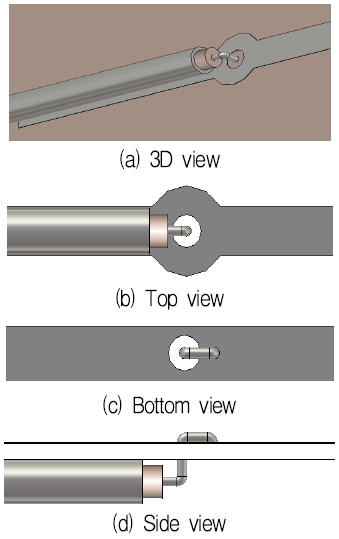
Next, we consider the problem of feeding the dipole antenna with a collinear coaxial cable. Fig. 11 shows the quadruple-arm dipole antenna fed by a coaxial cable. A transition between a coaxial cable to a parallel strip line is employed and its structure is shown in Fig. 12.
The outer conductor of the coaxial cable is directly connected to one of the strips of the parallel strip line and the center conductor is connected to the other strip through an insulated hole, around which a circular pad is employed to compensate for the discontinuity in the transition.
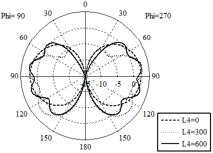
Fig. 13 shows the dimensions of the parameters for impedance matching of the dipole antenna fed by the coaxial cable. The position of the transition L2 from the horizontal feed line, and the length L3 of the open stub are adjusted for impedance matching. The length L4 of the coaxial cable beyond the printed circuit board is varied to study its effect on the antenna's gain pattern. Parameters of the coaxial cable used in the design are as follows:
Dielectric: dia. 1.65 mm, ϵr = 2.1, tanδ = 0.0002
Center conductor: dia. 0.5 mm
Outer conductor: inner dia. 1.65 mm, outer dia. 2.20mm
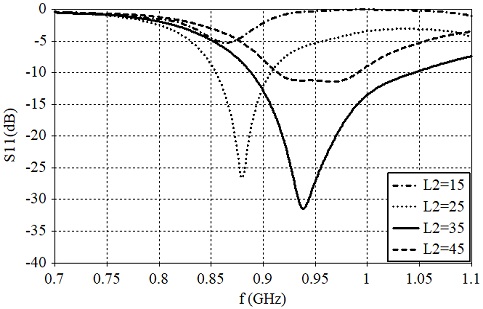
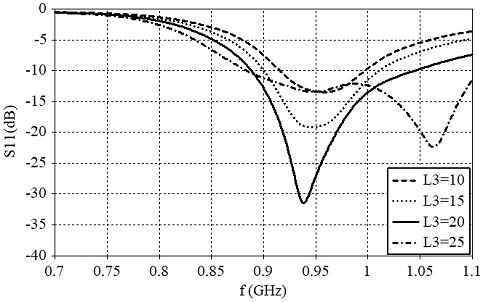
Fig. 14 shows the reflection coefficient versus the transition position L2. The optimum value of L2 is 35 mm. Fig. 15 shows the effect of the stub length L3 on the reflection coefficient. The optimum value of L3 is 20 mm.
Fig. 16 shows the effect of the width W0 of the vertical feed line strip. The optimum value of W0 is 2.4 mm corresponding to the 50-ohm characteristic impedance.
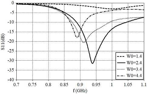
Reflection coefficient of the dipole antenna fed by a coaxial cable versus the parallel strip line width
When a half-wave dipole is fed by a collinear coaxial cable, the dipole's gain pattern is distorted by the radiation from the current flowing on the outer surface of the coaxial cable.
When the current on the coaxial cable surface is large enough, the dipole's gain pattern is greatly distorted resulting in many nulls in the gain pattern. Fig. 17 shows the gain pattern versus the coaxial cable length L4. One can observe appreciable levels of the pattern distortion. The suppression of the dipole's radiation pattern due to the coaxial current is a separate topic which is not dealt with in this paper.
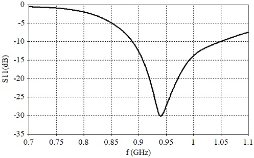
The performance of the dipole antenna fed by the coaxial cable is shown in Figs. 18 to 20 with the coaxial cable length L4 of 600 mm. Fig. 18 shows the reflection coefficient of the antenna. The reflection coefficient is less than -10 dB at 885-1050 MHz (165 MHz or 17% bandwidth). By optimally adjusting the parameters L2 and L3, a good impedance bandwidth has been obtained.
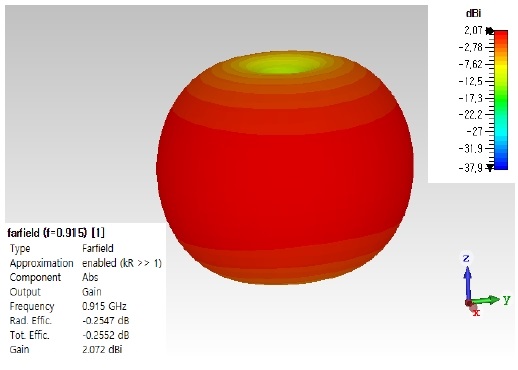
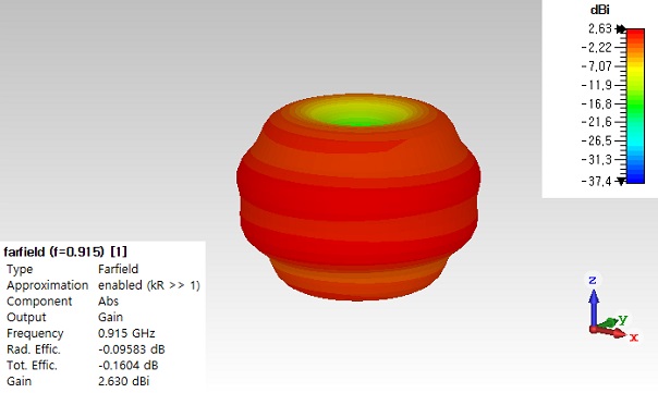
Fig. 19 shows the 3D gain pattern of the dipole antenna at 915 MHz. Due to the presence of the coaxial feeding cable, the gain pattern is distorted as can be seen by comparing Fig. 19 with Fig. 10.
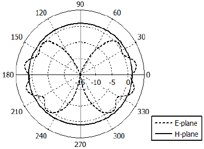
A more detailed gain variation versus angle can be seen in Fig. 20 where the E- and H-plane gain patterns of the antenna are presented. In the E-plane or the elevation plane, the useful antenna gain is obtained at angles from 60 degrees below the horizon to 50 degrees above the horizon.
In this angular range, the maximum and minimum gains are 2.6 dBi and -2.3 dBi respectively. In the case of the dipole structure of Fig. 1 without the coaxial cable, the maximum and minimum gain are 1.9 dBi and -5.2 dBi respectively in the same angular range. In the H plane, the maximum and minimum values of the antenna gain are 1.3 dBi and 1.0 dBi respectively.
Ⅲ. Conclusion
In this paper, a design method has been presented for a printed quadruple-arm dipole antenna fed first by a parallel strip line and next by a collinear coaxial cable. The structure without a coaxial cable has been designed first based on parametric analysis. It has been pointed out that the antenna impedance matching can effectively achieved by adjusting the H-arm spacing and the horizontal line strip width. A transition between a coaxial cable to a parallel strip line has been designed that has discontinuity compensation structures. The final design of the antenna operates at 885-1050 MHz with 17% bandwidth. Due to the coaxial feeding cable, the antenna's gain pattern is perturbed from that of a half-wave dipole. Reduction of the pattern distortion by a coaxial feeding cable will be treated in the future paper. The design method presented in this paper is useful in the implementation of a dipole antenna fed by a collinear coaxial cable. At lower frequencies, the printed dipole can be realized using wires without a printed circuit board.
References
-
Sang-Wo Jo, Li-Jian Jhang, and Bierng-Chearl Ah, "Design of a V-Dipole Antenna with an Integrated Balun", Journal of KIIT, Vol. 14, No. 12, pp. 71-78, Dec. 2016.
[https://doi.org/10.14801/jkiit.2016.14.12.71]

-
X. Li, L. Yang, S.-X. Gong, Y.-J. Yang, and J.-F. Liu, "A compact folded printed dipole antenna for UHF RFID reader", Progress In Electromagnetics Research Letters, Vol. 6, pp. 47-54, Jan. 2009.
[https://doi.org/10.2528/PIERL08121303]

- I.-G. Lee and I.-P. Hong, "Design of a film-type dipole antenna using a director element at UHF ISM band", JKIIT, Vo. 9, No. 9, pp. 77-82, Sep. 2011.
-
A. J. Fenn, P. T. Hurst, J. D. Krieger, J. S. Sandora, and L. I. Parad, "Ultrawideband VHF/ UHF dipole array antenna", 2010 IEEE International Symposium on Phased Array Systems and Technology, Waltham, MA, USA, pp. 79-82, Oct. 2010.
[https://doi.org/10.1109/ARRAY.2010.5613390]

- C.-T. Tai and S. A. Long, "Chapter 4 Dipoles and Monopoles", in Antenna Engineering Handbook, 4th Edition, J. L. Volakis Ed., New York: McGraw-Hill, 2007.
- D. Leeson, "The story of the broadband dipole", QEX, pp. 18-22, Nov./Dec. 2018.
- R. D. Straw Ed., "Chapter 7 Multiband Antennas", The ARRL Antenna Book, 21st Edition, ARRL, 2007.
-
Y. Cui, X. Gao, H. Fu, Q.-X. Chu, and R. Li, "Broadband dual-polarized dual-dipole planar antennas", IEEE Antennas and Propagation Magazine, Vol. 59, No. 6, pp. 77-87, Dec. 2017.
[https://doi.org/10.1109/MAP.2017.2753038]

-
Y. F. Li, B. H. Zeng, C. W. Chen, D. C. Chang, Z. R. Li, J. B. Liu, and H. B. Liang, "High performance planar sleeve dipole array antenna with directional radiation", Progress In Electromagnetics Research C, Vol. 21, pp. 169-177, Jul. 2011.
[https://doi.org/10.2528/PIERC11032104]

-
M. Straughn and C. C. Chen, "Series-fed planar dipole array antenna", Proc. 2017 IEEE Int. Symp. Antennas Propagat., San Diego, CA, USA, pp. 2153-2154, Jul. 2017.
[https://doi.org/10.1109/APUSNCURSINRSM.2017.8073119]

- X. Yu, D. Ni, and W. Wang, "An omnidirectional high-gain antenna element for TD-SCDMA base station", 2006 7th International Symposium on Antennas, Propagation & EM Theory, Guilin, China, pp. 1-4, Oct. 2006.
-
Z. Zhang, G. Fu, S. Gong, S. Zuo, and T. Ran, "Printed 6-element dipole array antenna for omnidirection applied in WiMAX", Proc. 6th Int. Conf. Wireless Comm. Networking Mobile Comp. (WiCOM), Chengdu, China, pp. 1-4, Sept. 2010.
[https://doi.org/10.1109/WICOM.2010.5600105]

-
Z. Y. Zhang and C. B. Zhang, "Wideband omnidirectional printed dipole antenna with coupling feed for wireless communication applications", Progress In Electromagnetics Research C, Vol. 38, pp. 89-99, May 2013.
[https://doi.org/10.2528/PIERC13012010]


2012. 1 ~2014. 1 : M. S. Degree, Electronic Eng., Mongolian University of Science and Technology
2019. 3 ~ present : Ph. D. Student, Radio and Communications Eng., Chungbuk National University
Research interests : Antennas, Microwave

2016. 8 : M. S. Degree, Radio and Communications Eng., Chungbuk National University
2018. 8 : Ph. D. Degree, Radio and Communications Eng., Chungbuk National University
2018. 8 ~ 2019. 8 : Postdoctoral Researcher, Radio and Communications Eng., Chungbuk National University
2019. 8 ~ present : Researcher, Gammanu Co.
Research interests : Antennas, Microwave

1992. 12 : Ph. D., Electrical Eng., University of Mississippi.
1992 ~ 1994 : Researcher, Agency for Defense Development
1995 ~ present : Professor, Radio and Communications Eng., Chungbuk National University
Research interests : Antennas, Applied EM

