Full Waveguide-band E-plane Power Divider with High Output Power Ratio
Abstract
This paper presents a new E-plane power divider with high output power ratio that operates over the full rectangular waveguide band. The proposed divider consists of an E-plane junction with rounded corners and a smoothly tapered septum. Output ratios of up to 10 are realized by offsetting the septum while output power ratios greater than 10 are achieved by additionally reducing the broad-wall width in the output waveguides with smaller power. Optimum dimensions of the proposed divider are obtained using a commercial electromagnetic-wave simulation tool. A design is given for a power divider in the WR-10 waveguide that has reflection coefficient of less than –20 dB over 75-110 GHz and output power ratios up to 100 at 75 GHz.
초록
본 논문은 사각형 도파관 전대역에서 동작하며 큰 출력비를 가지는 전계면 전력분배기를 제안한다. 제안된 분배기는 모서리가 둥글게 처리된 전계면 접합과 부드럽게 테이퍼된 격벽으로 구성된다. 출력비가 10까지의 경우 격벽의 오프셋을 통하여 얻고 10 이상의 출력비는 추가적으로 전력이 더 작은 출력 도파관의 광벽의 폭을 줄임으로써 얻는다. 상용 전자파 시뮬레이션 툴을 사용하여 제안된 분배기의 최적 치수를 얻었다. 75-110 GHz에서 -20 dB 이하의 반사계수를 가지며 75 GHz에서 100까지의 출력비를 가지는 WR-10 도파관의 전력 분배기의 설계를 제시하였다.
Keywords:
power divider, E-plane, rectangular waveguide, full waveguide band, high output power ratioI. Introduction
The power divider is one of the building blocks of waveguide components such as multiplexers, transmitters and receiver modules and array feed networks. Wideband power dividers with high output power ratio are often required in the feed network of the array of waveguide radiators [1][2]. Full waveguide-band power dividers have been investigated for H-plane [3] and E-plane [4] geometries. Literature on wideband power dividers with high output ratio is quite limited. Gómez and co-workers presented an E-plane gamma-junction power divider with output ratios of up to 10 [5], while Huang and co-workers investigated an E-plane T-junction power divider with output ratios of up to 4 [6].
In this paper, we present a new E-plane power divider that provides the output ratio of up to 100. The proposed power divider is structurally simple and can easily be fabricated using split-block technique or metal casting. The design and performance of the proposed power divider are presented below.
Ⅱ. Power Divider Structure
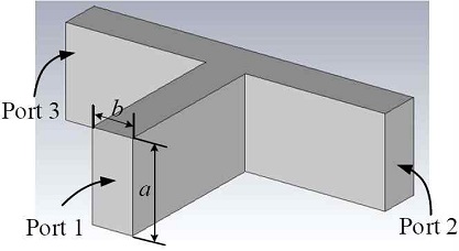
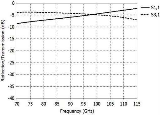
The E-plane junction power divider in a rectangular waveguide shows high reflection since it has large junction discontinuity reactance and no measure for input impedance matching. Fig. 1 shows a waveguide E-plane junction divider whose reflection coefficient is shown in Fig. 2 [7].
In Fig. 2, we see that the reflection coefficient of an uncompensated E-plane junction in WR-10 waveguide ranges from -8 dB at 75 GHz and -3 dB at 110 GHz. Clearly the E-plane junction requires matching structures if it is to used as a power divider. The E-plane junction can be compensated over narrow or wide frequency bandwidths. In this paper we present an E-plane power divider structure that provides reflection of less than -20 dB and high output power ratio over the full bandwidth of the WR-10 waveguide.
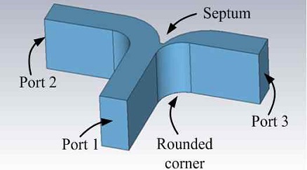
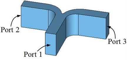
Fig. 3 shows the structure of the proposed power divider. The power divider consists of a T-junction with rounded corners and a smoothly tapered septum. The output waveguides are denoted by Port 2 and Port 3, whose output power is P2 and P3, respectively. Output power ratios P2/P3 of up to 10 are achieved by offsetting the septum as shown in Fig 3. The maximum offset is dictated by the smallest possible gap between the septum tip and the rounded corner that can accurately be fabricated.
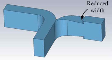
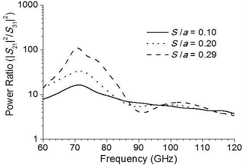
For power ratios higher than 10, the broad-wall width of the Port 3 waveguide is linearly tapered and directly connected to the output standard waveguide for as shown in Fig. 4. High output power ratios are in effect achieved by reducing the broad-wall width of the Port 3 waveguide below the cut off value.
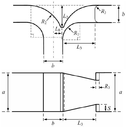
Fig. 5 shows design parameters of the proposed power divider. Rounded corners of the junction have radius R1 while the septum has a circular taper of radius R2. The sharp tip of the septum is removed such that the septum has length L2. The septum offset L0 from the center line controls the output power ratio.
For output power ratios of greater than 10, the broad-wall width of the Port 3 waveguide is linearly reduced by 2S over a length of L3. For split-block fabrication using an end mill with a cut along the center line of the broad wall, corners in the step are rounded with radius R3 (0.25 mm) [8]. Parameters R1, R2 , and L2 are kept constant for all values of output power ratios.
Ⅲ. Power Divider Design
Design of the proposed power divider is carried out using a commercial electromagnetic-wave simulation tool (CST Studio Suite). With R1 of about 0.7R2 and L0 equal to 0, R2 and L2 are adjusted for reflection coefficient of less than –20 dB over the operating frequency range 75-110 GHz of the WR-10 waveguide.
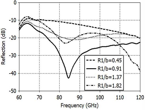
Fig. 6 shows the divider with no septum offset for determining the values of R1, R2, and L2. First the effect of R1 on the input reflection coefficient is investigated with R2 and L2 set at their optimum values 1.78b and 1.29b respectively.
Fig. 7 shows the input reflection coefficient (S11) versus R1. The optimum value of R1 is 0.91b giving the input reflection coefficient less than -20 dB at 74-120 GHz. Notice that larger values of R1 does not result in smaller reflection since the optimum value of R1 is also related the values of R2 and L2.
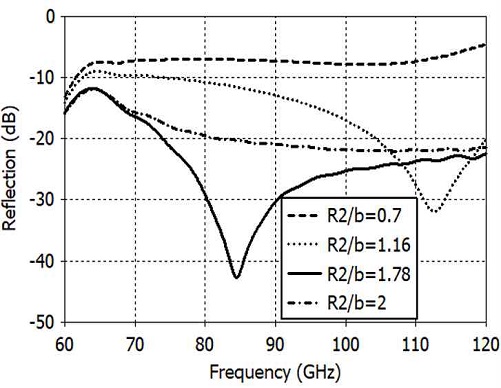
Next the input reflection is calculated for various values of R2. Fig. 8 shows the result. The optimum value of R2 is 1.78b. Larger values of R2 does not result in smaller reflection since in this case the septum reduces the narrow-wall width of the branching output waveguides. Rather sharp reduction to -42 dB of the reflection at 85 GHz is caused by a mutual resonant cancellation of discontinuity reactances of the divider junction.
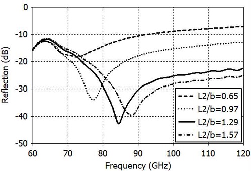
Fig. 9 shows the input reflection versus L2. Smaller values of L2 make the septum center edge flat and wide while larger values make the septum center edge sharper. The value of L2 is same as R2, the septum edge will be sharp as a razor's edge, which is not preferable in manufacturing the power divider. The optimum value of L2 is 1.29b
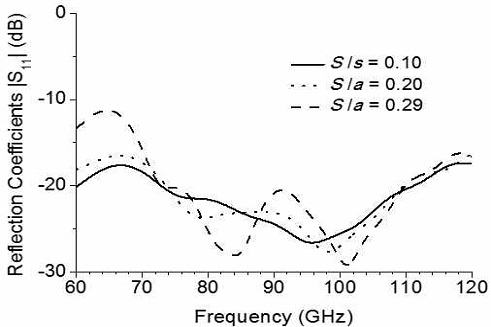
For output power ratios P2/P3 of up to 10, only the septum offset L0 is adjusted. For P2/P3 greater than 10, L0 is set at the value for P2/P3 = 10 and the taper step S is adjusted with the taper length L3 fixed at about 1.2a (a: the broad-wall width). The input reflection coefficient at Port 1 remains less than –20 dB for all output power ratios.
The proposed concept is applied to the design of a power divider for the WR-10 waveguide operating at 75–110 GHz. Table 1 shows the dimensions of the designed power divider normalized by the narrow wall width b.
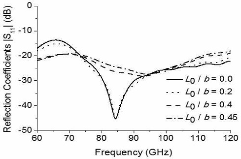
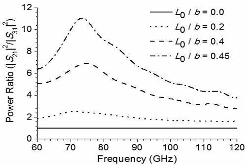
Optimum parameters for R1, R2, and L2 have been obtained using the divider with a symmetric septum shown in Fig. 6. The power divider with unequal output power ratios is obtained by offsetting the septum of the structure shown in Fig. 3. The reflection coefficient and the output power ratio are calculated for various values of the septum offset L0 and plotted in Figs. 10 and 11.
Figs. 10 and 11 show the reflection coefficient and the output power ratio of the structure of Fig. 3 while Figs. 12 and 13 show those of Fig. 4. The input reflection coefficient in all cases is less than –20 dB at 75-110 GHz. The output power ratio is maximum at 75 GHz and gradually decreases as the frequency increases. The maximum output power ratio is about 100 at 75 GHz and 4 at 110 GHz.
The output power ratio can be increased if the input reflection is allowed to increase up to –15 dB. With additional impedance matching structures such as irises, posts and steps in waveguide width and/or height, one can achieve higher output power ratios while keeping the input reflection below –20 dB. With proper impedance matching, power ratios can arbitrarily be increased by increasing the output waveguide taper while keeping reflection coefficient less than a specified value.
Ⅳ. Conclusion
In this paper, we presented a new E-plane power divider operating over the full rectangular waveguide band with maximum output power ratios of up to 100. Full-band operation is realized with a smooth tapered septum while output power ratio of greater than 10 is obtained by reducing the width of the broad wall in one of the output waveguides. A design has been presented for the proposed power divider with reflection coefficient of less than -20 dB and power ratio from 4 to 100 over the full waveguide band (75-110 GHz) of WR-10. The proposed power divider offers high output power ratio with simple structure. The proposed power divider concept can be applied to the design of waveguide components where the power needs to be divided over wideband with high ratios.
References
- J. Uher, J. Bornemann, and U. Rosenberg, "Waveguide Components for Antenna Feed Systems: Theory and CAD", Artech House, Boston, MA, pp. 343-369, 1993.
- W. Qi, S. Qiang, W. Yidong, Z. Xiaodi, and X. Baosen, "Design of N-way high power combiner based on E-plane stepped waveguide T-junction", Proc. 2018 IEEE MTT-S Int. Wireless Symp. (IWS), Chengdu, China, 6-10 May 2018.
-
P. Zhao, S. Liu, and I. Chen, "A full bandwidth H-plane power divider worked in millimeter wave band," 15th Int. Conf. Electron. Packag. Tech., pp. 1383-1384, Chengdu, China, 12-15 Aug. 2014.
[https://doi.org/10.1109/ICEPT.2014.6922909]

- A. R. Kerr, "Elements for E-plane split-block waveguide circuits", ALMA Memo 381, pp. 4-5, 2001.
-
I. Gómez, L. de Haro, B. Galocha, B, and J. L. Besasa, "Optimized power dividers based on E-plane T-junctions", Microw. Opt. Tech. Lett., Vol. 31, No. 2, pp. 118-123, Feb. 2001.
[https://doi.org/10.1002/mop.1375]

- G. L. Huang, S. G. Zhou, and T. H. Chio, "Development of a symmetric waveguide T-junction power divider with equal-phase characteristic", ACES Jour., Vol. 31, No. 3, pp. 309-314, Mar. 2016.
-
Y. Bang, G.-Y. Ariunbold, and B.-C. Ahn, "A new E-plane T-junction waveguide power divider employing a dielectric insert", Journal of KIIT, Vol. 20, No. 1, pp. 121-128, Jan. 2022.
[https://doi.org/10.14801/jkiit.2022.20.1.121]

-
D. H. Jun, M. S. Jung, and B. C. Ahn, "Design of a W-band groove polarizer", Journal of KIIT, Vol. 14, No. 4, pp. 79-84, Apr. 2016.
[https://doi.org/10.14801/jkiit.2016.14.4.79]


2019. 2 : B. S. Degree, Communication and Information Eng., Chungbuk National University
2019. 3 ~ present : M. S. Student, Radio and Communications Eng., Chungbuk National University
Research interests : Microwave circuits

2019. 2 : M. S. Degree, Radio and Communications Eng., Chungbuk National University
2019. 3 ~ present : Ph. D. Student, Radio and Communications Eng., Chungbuk National University
Research interests : Antennas, RF, Microwave

1987. 2 : B. A. Degree, Management, Sungkyunkwan University
2020. 9 ~ present : M. S. Student, Radio and Communications Eng., Chungbuk National University
Research interests : Antennas, RF, Microwave

1992. 12 : Ph. D., Electrical Eng., University of Mississippi.
1992 ~ 1994 : Researcher, Agency for Defense Development
1995 ~ present : Professor, Radio and Communications Eng., Chungbuk National University
Research interests : Antennas, Applied electromagnetics

