Design of a High-Performance 35GHz Monopulse Lens Antenna
Abstract
The lens antenna is one of favorable types of antenna at millimeter-wave frequencies since it is structurally simple and of small size. This paper presents a design of a high-performance 35GHz monopulse lens antenna with high aperture efficiency and low sidelobes for missile seeker applications. First, a lens is designed based on the antenna requirements. Next, a monopulse feed is designed utilizing tapered dielectric rods. For ease in the implementation of the monopulse comparator network, a 5-element configuration is adopted where the sum-channel element is separated from difference-channel elements. Finally the monopulse feed and the lens are combined to complete the antenna design. The designed antenna with a 16-wavelength diameter aperture has the sum-channel performance of 32.3dBi gain, 4.24° beamwidth, -28.4dB sidelobe level, and the difference-channel performance of 29.0dBi gain, 2.36° cross-over angle, -23.5dB sidelobe level, and null depth of greater than 40dB.
초록
렌즈 안테나는 구조적으로 단순하고 크기가 작아서 밀리미터파 대역에서 적합한 안테나 형태 중의 하나이다. 본 논문에서는 유도탄 탐색기용으로 높은 개구효율과 낮은 부엽을 가지는 고성능 35GHz 모노펄스 렌즈 안테나의 설계를 제시하였다. 첫째, 안테나 요구사항을 토대로 렌즈를 설계하였다. 다음으로 테이퍼진 유전체봉을 이용하여 모노펄스 피드를 설계하였다. 모노펄스 비교기 구현의 용이성을 위하여 합 채널 소자가 차 채널 소자와 분리된 5 소자 구조를 선택하였다. 마지막으로 모노펄스 피드와 렌즈를 결합하여 안테나 설계를 완성하였다. 16 파장 직경의 개구를 가지는 설계된 안테나는 이득 32.3dBi, 빔폭 4.24°, -28.4dB 부엽준위의 합 채널 특성을 가지며, 이득 29.0dBi, 교차각 2.36°, 부엽준위 -26dB, 영점 깊이 40dB 이상의 차 채널 특성을 가진다.
Keywords:
35GHz, lens antenna, monopulse, missile seekerI. Introduction
The monopulse antenna is widely used in missile seeker radars due to its high accuracy and fast response. In small diameter missiles, millimeter waves, especially Ka-band and W-band, are employed for increased angular resolution[1]-[4]. Monopulse seeker antennas are usually realized in the form of waveguide slot arrays[5][6], printed dipole arrays[7], microstrip patch arrays[8], and Cassegrain reflectors[9].
With a dielectric lens, a high-gain antenna can be realized without a complicated feed network. The lens antenna has such advantage as structural simplicity and the possibility of precision fabrication. Its drawbacks include relatively large axial length and non-small weight. Existing works on monopulse antennas employing the dielectric lens are limited[10]-[12].
Naratov and co-workers presented a combined structure of a Cassegrain reflector and a dielectric lens for the detection of targets at long range and for the fast tracking of close-range targets[10]. Zhang and Dou employed a zoned dielectric lens antenna in their design of a sub-millimeter monopulse antenna[11]. Wang and Dou presented a full-wave analysis of a monopulse dielectric lens antenna[12].
In this paper, we present a design of a high-performance 35GHz monopulse antenna with high aperture efficiency and low sidelobes. First, the design requirements and the antenna structure are presented followed by the optical design of a dielectric lens and the feed design. Finally the feed and the dielectric lens are combined to obtain a final design of the proposed antenna. The widely used CST Studio SuiteTM has been employed in the design.
Ⅱ. Antenna Structure
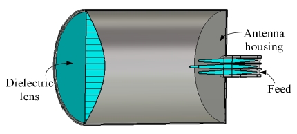
Table 1 shows the design requirements of the monopulse antenna. The antenna diameter is 140mm (16.3 wavelengths). Then the antenna's expected gain will be 31.2dBi assuming 50% aperture efficiency and the expected beamwidth is 4.6° as given by 75⋋/Dm. The above values are expected minimum and the requirements in Table 1 are higher than those values. Fig. 1 shows the structure of the designed antenna. The antenna consists of a dielectric lens, a monopulse feed, and an antenna housing made of metal. The dielectric lens transforms a spherical wave radiated by the feed into a planewave. A preferable material for the lens would have low dielectric constant and small loss. The focal length of the lens is about same as the lens diameter. The longer focal length results in better antenna performance since the angle of incidence at the lens surface does not vary much.
The monopulse feed is placed in the convex side of the lens with its phase center at the focus of the lens. The monopulse feed consists of five dielectric rods fed by a square waveguide and generates a sum pattern, an elevation difference pattern, and an azimuth difference pattern.
To form the above three patterns, a monopulse comparator is required, the design of which is not treated in this paper.
The metal housing protects the lens and the feed against the environment. It also places the lens and the feed at their prescribed locations. The side wall of the metal housing introduces some perturbation to the antenna performance by reflecting the portion of the radiated wave not captured by the lens. This can be remedied by lining the side wall with a thin absorbing material.
Ⅲ. Lens Design
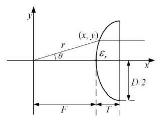
Fig. 2 shows the dimensional parameters and the coordinate system of the lens. The convex hyperbolic surface facing the feed transforms a spherical wave into a planewave which travels in the direction parallel to the lens axis. The planewave is normally incident on the flat surface of the lens and travels without its changing direction after exiting the lens surface.
The equation for the hyperbolic surface can be derived using the theory of geometrical optics. A point (r, θ) or (x, y) on the hyperbolic surface is given by the following equation in polar or Cartesian form[14].
| (1) |
| (2) |
| (3) |
With low dielectric constant material, the thickness at the lens center becomes large and the incidence angle of the feed's wave may be excessively large at the lens edge. The problem can be alleviated by using a large focal length. If the focal length needs to be small, a high dielectric constant material may be used together with a quarter-wave matching layer on both surfaces.
In our design, we used the cross-linked polystyrene (Rexolite 1422) as the lens material whose dielectric constant and loss tangent are 2.52 and 0.0007 respectively. The lens dimensions are D = 140mm, F = 135.47mm, and T = 25.53mm. The angle of the feed's wave at the lens edge is then
| (4) |
Ⅳ. Feed Design
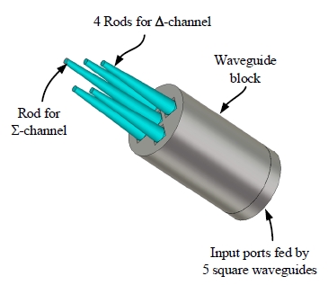
Fig. 3 shows the monopulse feed used in our design. It consists of five tapered dielectric rods fed by a square waveguide. We adopted a design given by Shen and co-workers[13]. The dielectric material for the rods is same as that for the lens. The length of rods is adjusted to obtain a required 10-dB illumination beamwidth for the lens. In our design the illumination half-angle is 23.5° and the length outside the waveguide (L1) of the center rod is 45.45mm (5.3 wavelengths).
The initial rod diameter at the waveguide aperture (d1) of 5.64mm (0.66 wavelength) is tapered to the final diameter at the tip d2 = 2.14mm (0.38d1). The length outside the waveguide (L2) of the side rods is 34.08mm (0.75L1). The distance between the centers of the dielectric rods is 7.25mm (0.85 wavelength).
The gain of the center rod is increased by the presence of the side rods. The width of the square waveguide feeding the dielectric rod is same as the diameter of the dielectric rod. Inside the square guide, the dielectric rod is tapered so that the empty square guide input port is impedance-matched to the square guide filled with a circular dielectric rod. The lengths of the rods can be adjusted so that the sum pattern gain varies from 12dB to 20dB with correspondingly narrower beamwidths.
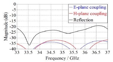
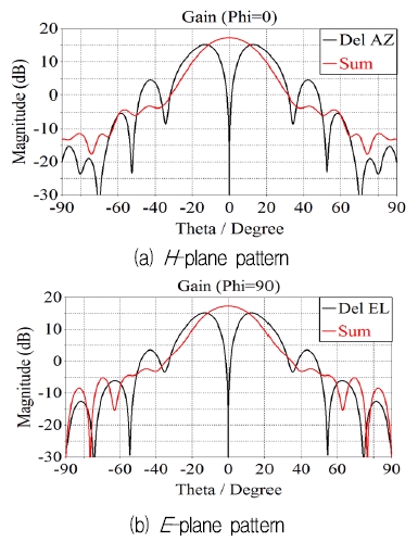
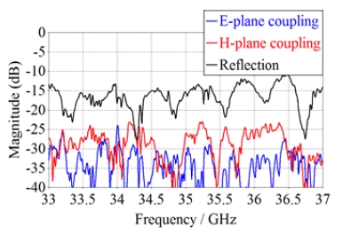
Fig. 4 shows the reflection coefficient of the central rod and the coupling coefficients between the central rod and the side rods in the absence of the lens. The sum-channel reflection coefficient is less than -20dB at 34.5~35.5GHz. The reflection coefficient of the side rods, not shown in Fig. 4, is also less than -20dB. The coupling between ports is less than -30dB in both planes. Fig. 5 shows the gain patterns at 35GHz of the feed with vertical polarization (with the electric field in the direction of the elevation difference pattern axis; phi = 90°)
The maximum gain of the sum pattern is 17.5dB, while it is 15.0dB for the azimuth and elevation difference patterns. The 10dB half-beamwidth (the lens illumination half-angle) of the sum pattern is 23.5°. The taper of the difference patterns at 23.5° is 4 dB. The cross-over angle of the sum and difference patterns is 11.6°, which is approximately half the illumination half-angle. The difference patterns have null depth greater than 40dB.
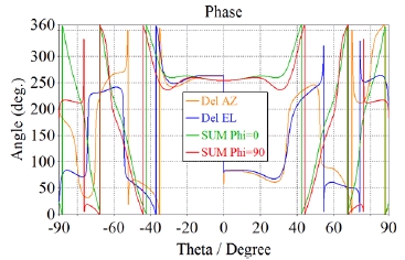
Fig. 6 shows the phase patterns of the feed. The phase center is located at 22.38mm (2.61 wavelengths) from the tip of the central dielectric rod toward the square guide. Within the illumination half-angle, the phase variation is less than 14° (±7° from the average) in the sum and difference patterns.
Ⅴ. Complete Antenna Design
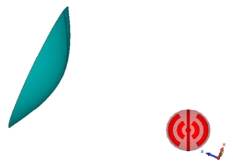
The lens and the feed are combined, and the gain patterns of the combined structure are calculated. Since the structure is electrically large, the exact simulation of the full structure takes too much time so that we obtained approximate results using a simplified model shown in Fig. 7. We removed the metal housing in Fig. 1 and illuminated the lens with the far-fields patterns of the feed (the far-field source in CST Studio Suite). The simplified model neglects multiple wave reflections and scattering by the lens, the feed and the metal housing. With the metal housing and the feed included in the simulation, moderate performance degradation is expected (for example, about 5~10dB increase in the feed reflection coefficient, gain reductions of a few tenths of dB, sidelobe increase of a few decibels).
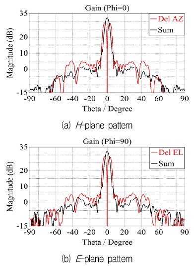
Fig. 8 shows the sum and difference patterns at 35GHz in the H- and E-planes. The sum channel has the following characteristics: 32.3dBi maximum gain (66% aperture efficiency), 4.24° beamwidth, and -28.4dB sidelobe level, while the difference channels have 29.0dBi gain, 2.36° cross-over angle, null depth greater than 40dB, and -23.5dB sidelobe level.
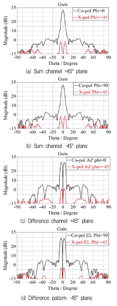
Fig. 9 shows the cross-polarization gain patterns of the lens antenna at 35GHz. The maximum cross-polarization level of the sum channel is -34dB, while that of the difference channels is -28dB.
The full antenna structure including the metal housing and the feed has been simulated, which took about 72 hours on a personal computer. Fig. 10 shows the reflection and transmission coefficients at the feed's input ports of the full antenna structure.
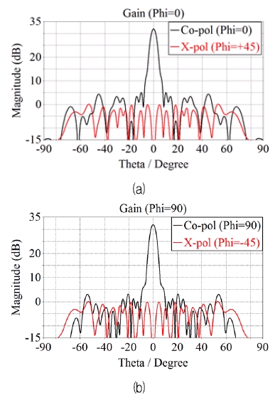
The reflection coefficient is increased by 9dB at 34.5~35.5GHz compared to the case of the simplified model of Fig. 7 while the transmission coefficients are increased by 8dB. Fig. 11 shows the sum channel co-and cross-polarized gains. The co-polarized gain is decreased to 31.9dB (0.4dB decrease) while the beamwidth is increased to 4.40° (0.14° increase) and the sidelobe level is increased by 1dB in the H-plane. Radiation of the cross-polarized wave is noticeably increased at angle from 5° to 80° off the main beam axis.
Ⅵ. Conclusion
In this paper, we presented a design of a high-performance monopulse lens antenna operating at 34.5~35.5GHz fed by a five dielectric-rod feed. First, the design of the lens has been presented followed by the feed design. Next, the feed and the lens were combined to obtain a final design of the proposed antenna. The designed antenna shows the sum channel gain of 32.3dBi gain, beamwidth of 4.24°, sidelobe level of -28.4dB, and cross polarization level of -34dB. The difference channel has gain of 29.0dBi, cross-over angle of 2.36°, null depth greater than 40 dB, sidelobe level of -23.5dB, and cross polarization level of -28dB. The multiple reflection and scattering increases the reflection coefficient and mutual coupling of the feed, and the cross polarization of the lens antenna. The proposed antenna is useful in the development of a millimeter-wave monopulse seeker.
References
-
H. G. Oltman, and M. E. Beebe, "Millimeter wave seeker technology", Proc. Guidance Control Conf., G. Beard, p148-151, Aug.), (1978.
[https://doi.org/10.2514/6.1978-1259]

-
L. P. Cecchini, E. Pizzingrilli, S. Russo, and U. F. D'Elia, "MMW active phased array seeker project for hit to kill engagement", Proc. IEEE Radar Conf., p1-6, Jun.), (2008.
[https://doi.org/10.1109/radar.2008.4720743]

-
S. Yumeng, C. Jie, G. Caihong, S. Bing, and Z. Yinqing, "The advanced simulation system for MMW imaging radar seeker onboard air-to-air missile", Proc. 8th Int. Conf. Sig. Proc., Nov.), (2006.
[https://doi.org/10.1109/icosp.2006.346037]

-
A. Pal, V. Harikrishna, N. R. Rao, J. V. Prasad, B. K. Mukhopadhyaya, and K. Veerabhadra, "Millimetric wave seeker for third generation antitank guided missiles", Def. Sci. J., 45(3), p225-228, Jul.), (1995.
[https://doi.org/10.14429/dsj.45.4123]

- J. M. Schuchardt, and D. J. Kozakoff, "Chapter 46 Seeker Antennas", in Antenna Engineering Handbook 4th Ed, J. Volakis Ed., (2007).
-
T. Li, H. Meng, and W. Dou, "Design of low sidelobe slotted waveguide monopulse antenna array", Proc. Asia-Pacific Conf. Antennas Propagat., p212-214, Jul.), (2014.
[https://doi.org/10.1109/apcap.2014.6992455]

-
H. G. Oltman, and D. A. Huebner, "Electromagnetically coupled microstrip dipoles", IEEE Trans. Antennas Propagat., 29(1), p151-157, Jan.), (1981.
[https://doi.org/10.1109/tap.1981.1142526]

-
H. Wang, D. G. Fang, and X. G. Chen, "A compact single layer monopulse microstrip antenna array", IEEE Trans. Antennas Propagat., 54(2), p503-509, Feb.), (2006.
[https://doi.org/10.1109/tap.2005.863103]

-
J. M. Lee, W. Noh, D. H. Kim, Y. T. Choi, and B. C. Ahn, "Design of a Cassegrain reflector for monopulse antenna", Journal of KIIT, 13(11), p1-8, Nov.), (2015.
[https://doi.org/10.14801/jkiit.2015.13.11.1]

- M. P. Natarov, V. V. Glamazdin, V. N. Skresanov, and A. I. Shubny, "Combined reflectorlens monopulse antenna", Proc. Int. Conf. Antenna Theory Tech., p251-254, Oct.), (2003.
- L. Zhang, and W. Dou, "Analysis and design of a quasi-optical monopulse antenna at submillimeter wavelengths", Terahertz Sci. Tech., 7(3), p145-149, Sep.), (2014.
- Z. X. Wang, and W. B. Dou, "Full-wave analysis of monopulse dielectric lens antennas at W-band", J. Infrared Milli Terahz Waves, 31, p151-161, Feb.), (2010.
-
A. Shen, B. C. Ahn, S. J. Shin, Y. H. Cho, and K. H. Oh, "Design of a W-band seeker antenna employing a dielectric-rod feed", Journal of KIIT, 16(2), p75-82, Feb.), (2018.
[https://doi.org/10.14801/jkiit.2018.16.2.83]


2013 : M.S. NTUU "Kyiv Polytechnic Institute"
2013 ~ 2014 : Research Engineer, PAO NPP "Saturn"
2015 ~ Present : Ph. D Student, Radio and Communications Eng., Chungbuk National University
Research interests : Antennas, microwaves devices and systens

2017 ~ Present : M.S Student, Radio and Communications Eng., Chungbuk National University
Research interests : Antennas

2010. 2 : M.S., Electronics Eng., Ajou University
1998. 1 ~ 2012. 6 : Principal Researcher, Samsung Thales Inc.
2015. 7 ~ 2015. 7 : Principal Researcher, Hanwha Thales Inc.
2012. 6 ~ Present : Principal Researcher, Hanwha Systems Inc.
Research interests : Antenna systems, millimeter-wave antennas

2009. 2 : B.S., Electronics, Ajou University
2016. 2 : Ph. D., Electronics, Ajou University
2016. 3 ~ 2016. 9 : Researcher, Hanwha Thales
2016. 9 ~ Present : Researcher, Hanwha Systems
Research interests : Antenna and propagation, radome electromagnetic analysis

1992. 12 : Ph. D., Electrical Eng., University of Mississippi
1992 ~ 1994 : Research Engineer, Agency for Defense Development
1995 ~ Present : Professor, Radio and Communications Eng., Chungbuk National University
Research interests : Antennas, applied EM


