Design of a W-Band Seeker Antenna Employing a Dielectric-Rod Feed
Abstract
W-band seekers find increasing applications in missile terminal homing in adverse weather conditions. W-band seekers typically employ a Cassegrain reflector antenna which requires a high-performance monopulse feed. This paper presents a design of a W-band monopulse seeker antenna fed by a new feed consisting of five dielectric rods. Compared to existing 4-horn feeds, a simple monopulse comparator can be used with the proposed feed. First an optical design of a Cassegrain antenna is presented that satisfies given specifications. Next, a feed is designed which consists of a longer dielectric rod at the center for sum pattern and four shorter dielectric rods for difference pattern placed at the top, bottom, left and right of the center dielectric rod. Finally, the dielectric-rod feed and the Cassegrain reflector are combined to realize a high-performance seeker antenna. The designed 38-wavelength diameter seeker antenna has sum pattern gain of 39.2dBi, beamwidth of 1.79°, side-lobe level of -20dB, and difference pattern gain of 36.4dBi, cross-over angle of 1.04°, side-lobe level of -26dB, and null depth of 47dB.
초록
불리한 기상조건에서 유도탄 종말 탄착용으로 W-대역 탐색기의 응용이 증가하고 있다. W-대역 탐색기에서는 보통 카세그레인 반사경이 사용되며 이 경우 고성능 모노펄스 피드가 요구된다. 본 논문에서는 5개의 유전체 봉으로 구성된 새로운 피드에 의해 급전되는 W-대역 모노펄스 탐색기 안테나의 설계를 제안한다. 기존의 4-혼 피드와 비교하여 제안된 피드의 경우 단순한 모노펄스 비교기를 사용할 수 있다. 우선 주어진 규격을 만족하는 카세그레인 안테나의 광학설계를 제시하였다. 다음으로 중앙에 위치한 합패턴용의 보다 긴 유전체 봉, 중앙 유전체봉의 상하좌우에 배치된 차패턴용의 보다 짧은 유전체 봉으로 구성된 피드를 설계하였다. 마지막으로 유전체봉 피드와 카세그레인 반사경을 결합하여 고성능 탐색기 안테나를 구현하였다. 직경 38파장의 설계된 탐색기 안테나의 합패턴은 39.2dBi의 이득, 1.79°의 빔폭, -20dB의 부엽준위, 차패턴은 36.4dBi의 이득, 1.04°의 교차각, -26dB의 부엽준위, 영점깊이 47dB를 가진다.
Keywords:
cassegrain reflector, W-band seeker, monopulse, cassegrain reflector, dielectric rodI. Introduction
Radar seekers are essential for the all-weather terminal homing in air-to-ground or air-to-air missiles. There have been worldwide development efforts in W-band radar seeker technologies as components become more available[1]. The monopulse reflector antenna is a good candidate for a high-performance seeker at W-band[2][3]. The design of a monopulse reflector feed is not simple because it requires a simultaneous optimization of sum and difference patterns. Typical monopulse reflector feeds include four-horn arrays[4], five-horn arrays[5], dielectric-rod arrays[6][7], and multi-mode single horn apertures[8].
In a four-element monopulse feed, all four elements are combined to form sum, azimuth and elevation difference patterns. A five-element monopulse feed is advantageous in simplifying the design of a monopulse comparator because sum and difference elements can independently be combined. Feeds employing five horns suffer from poor pattern performance and excessive blockage. It is because the aperture of a single horn is too large for the monopulse array geometry.
In this paper, we present a W-band seeker antenna based on the Cassegrain reflector with a new feed consisting of five dielectric rods. The proposed feed shows excellent pattern characteristics with minimal blockage of waves traveling toward the main reflector (and thus toward the feed) after being reflected by the sub-reflector. To the best of the authors' knowledge, the proposed five-dielectric-rod monopulse feed is new and has never been fully presented in the open literature.
First, the optical design of the reflector antenna is presented, followed by the feed design. Next, the feed and the reflector are combined to realize a highperformance W-band seeker antenna. The operating frequency of the designed antenna is not disclosed for reasons of military secrecy. The dimensions of the
designed antenna are specified in terms of the wavelength at the center frequency of operation. The widely used Microwave StudioTM by CST has been employed in the design.
Ⅱ. Reflector Optical Design
Table 1 shows the specifications of a W-band seeker antenna to be designed. The antenna diameter is 38 wavelengths and the antenna gain will be 38.5dBi assuming 50% aperture efficiency. The expected beamwidth is 1.97° as given by the following equation
| (1) |
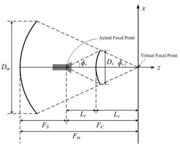
Fig. 1 shows the dimensional parameters of a Cassegrain reflector. With the main reflector diameter given, the main reflector's focal length is determined first. It is required for the seeker antenna to have its main beam scannable by ±9° by rotating the main reflector around its paraboloid vertex. For this purpose, it is advantageous to make the main reflector as flat as possible by using a large focal length for a given reflector diameter. In this paper, a focal length of about 30 wavelengths is chosen, which corresponds to the F/D ratio of 0.78.
The half subtended angle ϕv seen from the main focus (the virtual focal point in Fig. 1) to the main reflector edge is 35.0° as obtained from the following equation.
| (2) |
A small sub-reflector reduces the aperture blockage and the side-lobe level, while it increases the diffraction loss. A small sub-reflector requires a narrow-beam feed with a large aperture, or the placement of a small-aperture feed close to the subreflector. In either case, the blockage of subreflector- reflected waves by the feed is a problem. Therefore the choice of the sub-reflector diameter is a compromise between two conflicting requirements. In our design the sub-reflector diameter of 6.27 wavelengths is chosen.
The half subtended angle ϕr seen from the subreflector focal point (we will call it the sub-focus) is set at 25.5° based on a preliminary design of the feed. The sub-reflector focal length (Lr + Lv) / 2 is 11.28 wavelengths as obtained from the following equation
| (3) |
The remaining parameter is the ellipticity e of the hyperbolic sub-reflector given by the following equation.
| (4) |
The ellipticity is 6.05 in our design. Table 2 shows the dimensions of the designed Cassegrain reflector antenna.
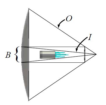
One of the important requirements in the design of an axisymmetric dual reflector antenna is that the feed blockage does not exceed the sub-reflector blockage. The concept is shown in Fig. 2, where the focal point of the main reflector and its ray boundaries(I, O) are shown. The inner boundary(I) is determined by the sub-reflector diameter. For the feed blockage to be less than the sub-reflector blockage(B), no part of the feed should be inside the inner ray boundary(I).
Ⅲ. Feed Design
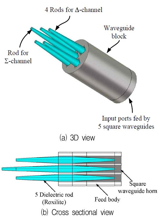
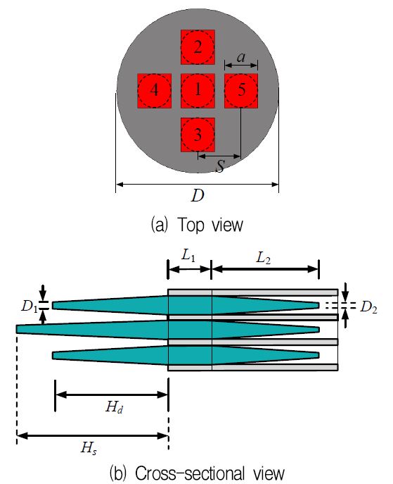
Fig. 3 shows the structure of the five-dielectric-rod feed proposed in this paper. The radiating element is a tapered circular dielectric rod fed by a square waveguide. The square waveguide is employed since it is easier to design a monopulse comparator in waveguide medium. The center element is for the sum pattern, the right and left elements are for the azimuth difference pattern, the top and bottom elements are for the elevation difference pattern.
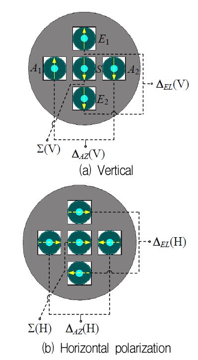
Fig. 4 shows a scheme for combining dielectric rods to form a sum pattern, azimuth and elevation difference patterns in vertical and horizontal polarizations. The polarization separation can be done with an orthomode transducer or with a set of two orthogonal probes. The anti-phase excitation (i.e., with a 180° phase difference) of two square waveguides for a difference pattern can be conveniently realized by anti-symmetrically placing the waveguide coupling structures and by combining their outputs with a same phase.
With the proposed feed, the monopulse network is greatly simplified since only two elements need to be combined to form a difference pattern. In a four-element feed, one has to combine all four elements to form a sum and two difference patterns which requires the use of highly complicated structures. The design of the monopulse comparator for the proposed feed will be presented in a separate paper.
Fig. 5 shows dimensional parameters of the proposed feed. The dielectric rod is tapered both inside and outside the square waveguide. The inside taper is for reducing reflection seen from the square waveguide, while the outside taper is for matching the dielectric rod's traveling-wave impedance to the planewave impedance and for reducing the side-lobe level.
The cross-linked polystyrene (Rexolite 1422, ϵr = 2.53, tanδ = 0.0008) is used as the dielectric rod material. The square guide wall width a (same as the diameter of the dielectric rod) is chosen so that only TE10 and TE01 modes can propagate in the air-filled guide while the guided wavelength λg in the dielectric rod at the square waveguide aperture (i.e., at the launching point of the dielectric rod's traveling wave) is approximately 0.8 times the wavelength in vacuum (λ0).
The dielectric rod's diameter is tapered toward its end to reduce the reflection and the side-lobe level. The diameter of the dielectric rod end is chosen so that the wavelength of the rod's traveling wave is approximately λ0 at this point. The length of the dielectric rod is primary chosen for gain. When the rod length changes from 5 to 15 wavelengths, the gain varies from approximately 16dBi to 20dBi.
After the design of a single dielectric rod element, an array of five dielectric rods is formed as shown in Fig. 5. The spacing between two opposite dielectric rods is minimized so that the grating lobe occurs as far away as possible from the feed's boresight. The lengths of the sum and difference elements are adjusted for optimum sum and difference patterns.
It has been found that a good sum pattern can be obtained when the length of the difference elements is smaller than that of the sum element by about 25%.
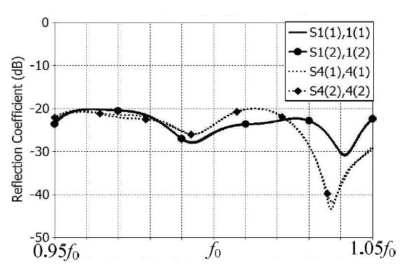
Next, a design is carried out for the taper of the dielectric rod inside the square waveguide. The taper length L2 and the taper end diameter D2 are determined for reflection coefficient of less than -20dB at 0.95f0-1.05f0, where f0 is the center frequency of operation. This level of the reflection coefficient can be obtained only when the end diameter D2 is sufficiently small. Table 3 shows the dimensions of the designed feed.
Fig. 6 shows the reflection coefficient of the designed feed. The port numbers are denoted in Fig. 5(a). The number in parentheses of the scattering parameters refers to the polarization. For example, S1(1),1(1) and S1(2),1(2) are the reflection coefficients at port 1 of the vertically and horizontally polarized waves, respectively. In Fig. 6, it is noted that the reflection coefficient of the designed feed is less than -20dB at all ports.
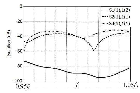
Fig. 7 shows the polarization and port isolation characteristics of the designed feed. In the sum element (port 1), the polarization isolation is greater than 70dB. Isolation between adjacent dielectric rod elements are greater than 30dB.
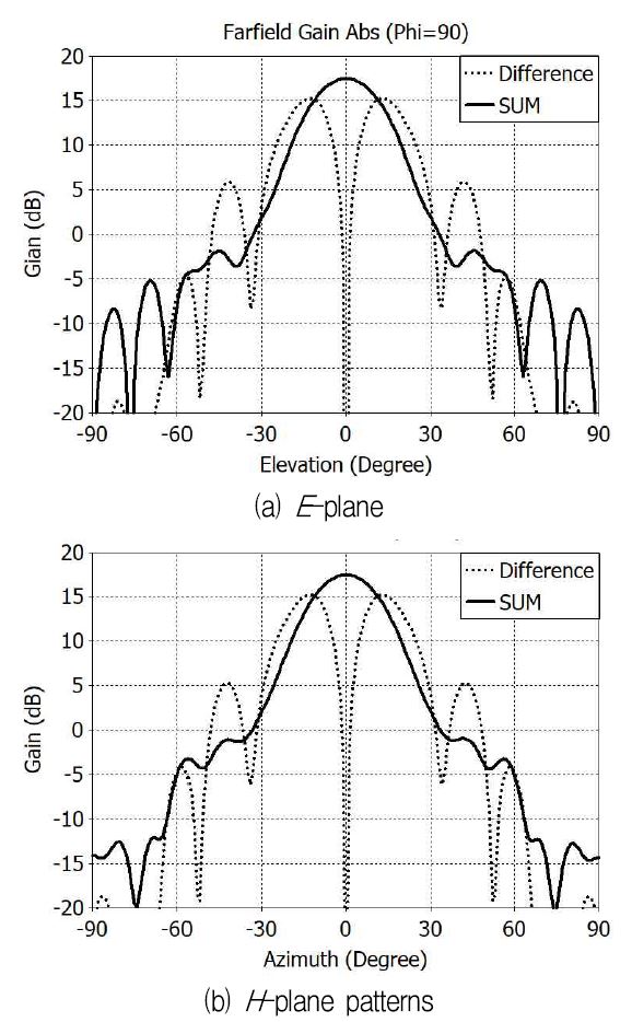
Fig. 8 shows the gain patterns of the designed feed in vertical polarization. The horizontal polarization patterns can be obtained by rotating the vertically polarized patterns by 90 degrees. In Fig. 8, one can notice that the E- and H-plane patterns are very similar to each other. This is due to the geometrical symmetry in the placement of dielectric rods and due to the excellent radiation pattern symmetry of the dielectric rod element. The sum pattern has gain of 17.5dBi, side-lobe level of -20dB, gain taper of 12.5dB at 25.5° (the half subtended angle of the sub-reflector seen from the sub-focus). The difference pattern has gain of 15.0dBi, side-lobe level of -9dB, gain taper of 5.0dB at 25.5°, and null gain of less than -20dBi.
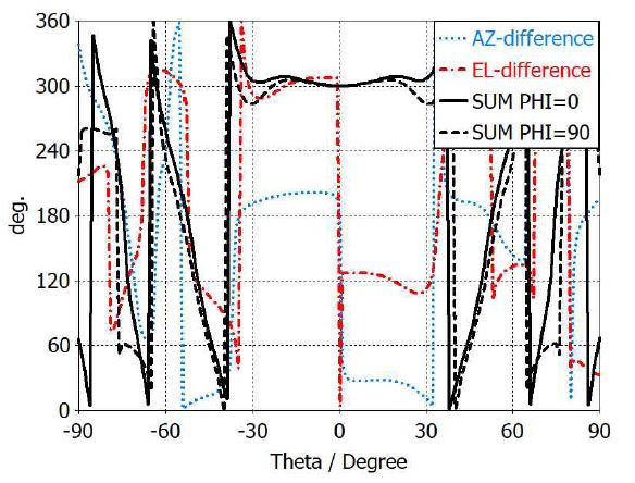
Fig. 9 shows the phase patterns of the designed feed. The phase center is located at 5.10 wavelengths away from the square waveguide aperture toward the sum element's tip. The phase errors of the sum and difference patterns are less than ±5° and ±8° respectively within 25.5° from the boresight.
Ⅳ. Seeker Antenna Design
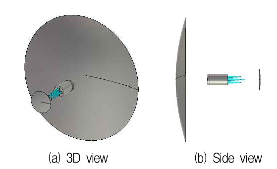
The designed feed is applied to the Cassegrain reflector antenna described in Section II. Fig. 10 shows a CAD model of the designed seeker antenna. In an actual prototype development, it is necessary to add feed support structures and a radome. The feed's phase center is almost at the tip of the center dielectric rod. One can notice that the sub-reflector is very thin and looks like a flat surface.
Calculation shows that the sub-reflector thickness is only 0.134 wavelength while the main reflector is 2.97 wavelengths thick. The feed diameter satisfies the minimum feed blockage condition depicted in Fig. 2.
In any axisymmetric Cassegrain reflector antenna, the increase of the feed reflection coefficient by waves reflected from the sub-reflector is an important issue. Multiple reflections between the sub-reflector and the main reflector contribute very little to the increase in the reflection coefficient of the feed.
Fig. 11 shows the reflection coefficient of the feed and the sub-reflector combination (that is, without the main reflector). The reflection coefficient of the sum and difference elements (elements 1 and 2 in Fig. 5(a)) are drawn in solid and dotted curves respectively. The reflection coefficient is increased from -20dB (Fig. 6) to -10dB in the sum element and to -15dB in the difference element.
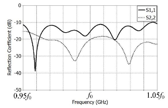
Feed reflection coefficient in the presence of the sub-reflector (Solid: sum element, dotted: difference element)
The gain pattern computation using the full structure requires enormous computing power and time. To find approximate far-field gain patterns, a combined structure of the sub-reflector and the main reflector is illuminated by the far-field pattern of the feed and sub-reflector combination. The sub-reflector is included in the gain pattern calculation to account for the scattering by the sub-reflector of waves reflected from the main reflector. This is an approximation since scattering by the feed is not included.
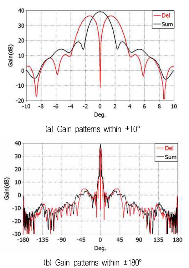
Fig. 12 shows the far-field gain patterns of the designed Cassegrain reflector antenna. Fig. 12(a) shows the sum and difference patterns drawn together. The sum pattern has maximum gain of 39.2dBi(59.6% aperture efficiency), side-lobe level of -20dB, and 3-dB beamwidth of 1.79°. Far-out side-lobe levels are less than -33dB. The difference pattern has maximum gain of 36.4dBi, side-lobe level of -26dB, cross-over angle (the point where the sum gain is equal to the difference gain) of 1.04°, and null depth of 47dB.
Far-out side-lobe levels are less than -31dB. The angle measurement accuracy of a monopulse seeker is given by
| (5) |
where θ0 is the cross-over angle (full width, not half), S/N is the signal-to-noise ratio at the receiver output, and k is a constant ranging from 1.5 to 2.3. The full angle θ0 between cross-over points is approximately same as the 3-dB beamwidth of the sum pattern.
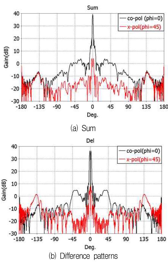
Fig. 13 shows the cross-polarized gain patterns of the designed antenna in the E plane. In the sum pattern, the maximum relative cross polarization level is -38dB while it is -28dB in the difference pattern.
Ⅴ. Conclusion
In this paper, we presented a design of a Cassegrain monopulse reflector antenna fed by a new five-dielectric-rod feed for W-band seeker applications. Compared with existing designs, the proposed feed offers excellent performance with minimal blockage. First, the Cassegrain optical design is carried out, followed by the feed design. The designed feed has good sum and difference gain patterns with excellent pattern symmetry and suitable edge taper. The Cassegrain optical design has been combined with the designed five-dielectric-rod feed to realize a high-performance W-band seeker antenna. The 38- wavelength diameter reflector antenna has excellent monopulse sum and difference pattern characteristics suitable for missile seeker applications. A next step in the development of a working W-band seeker antenna would be the design of a waveguide monopulse comparator and a radome. Concepts presented in this paper may find wide applications in the development of high-performance W-band seeker systems.
Acknowledgments
This work was supported by a grant-in-aid of HANWHA SYSTEMS in 2017.
References
- G. Beard, "Performance factors for airborne short-dwell squinted radar sensors", Ph.D. dissertation, Univ. College, London, Sept), (2010.
-
J. M. Lee, J. W. Noh, D. H. Kim, Y. T. Choi, and B. C. Ahn, "Design of a Cassegrain reflector for monopulse antenna", Jour. KIIT, 13(11,), p1-8, Nov), (2015.
[https://doi.org/10.14801/jkiit.2015.13.11.1]

-
P. Zheng, B. Hu, S. Xu, and H. Sun, "A W-band high-aperture-efficiency multipolarized monopulse Cassegrain antenna fed by phased microstrip patch quad", IEEE Antennas Wireless Propagat. Lett, 16, p1609-1613, Jul), (2017.
[https://doi.org/10.1109/lawp.2017.2653840]

-
P. Zheng, G. Q. Zhao, S. H. Xu, F. Yang, and H. J. Sun, "Design of a W-band full-polarization monopulse Cassegrain antenna", IEEE Antennas Wireless Propagat. Lett, 16, p99-103, Apr), (2017.
[https://doi.org/10.1109/lawp.2016.2558285]

- H. Meng, and W. Dou, "Design of diffractive Cassegrain antenna at W band", Proc. IEEE CIE Int. Conf. Radar, 1, p24-27, Oct), (2011.
- D. K. Lee, and J. H. Bang, "Broadband monopulse feed", Korean Patent, 10-1788516, Oct), (2017.
-
S. S. Qian, X. G. Li, and B. Q. Wang, "Ka band Cassegrain monopulse antenna fed by tapered rod antennas", Proc. 8th Int. Symp, Antennas Propagat. EM Theory, 1, p39-41, 2-5), Nov, (2008.
[https://doi.org/10.1109/isape.2008.4735134]

-
R. J. Liu, and W. B. Dou, "Design and analysis of 3mm multimode monopulse feed", Proc. Int. Conf. Microw. Millimeter Wave Tech, 1, p1-3, 18-21), Apr, (2007.
[https://doi.org/10.1109/icmmt.2007.381292]


2016. 2 : BS, Information and Communication Eng, Chungbuk National University
2016 ~ Present : MS, Radio and Communications Eng., Chungbuk National University
Research interests : Antennas, RF

1992. 12 : Ph. D., Electrical Eng., University of Mississippi.
1992 ~ 1994 : Researcher, Agency for Defense Development
1995 ~ Present : Professor, Radio and Communications Eng., Chungbuk National University
Research interests : Antennas, applied EM

1989 ~ 1995 : BS, Instrumentation and Measurement Eng. Hanyang University
1996 ~ 1998 : MS, Instrumentation and Measurement Eng. Hanyang University
1998 ~ 2002 : Ph. D., Instrumentation and Measurement Eng. Hanyang University
2003 ~ 2004 : Research Engineer, K1 Research Laboratory
2005 ~ 2013 : Research Engineer, Agency for Defense Development
2014 ~ Present : Principal Research Engineer, Defense Industry Technology Center
Research interests : Target tracking filter, radar signal processing algorithm, radar waveform and system design

2005. 2 : BS, Electronics, Sogang University
2012. 2 : Ph. D., Electronics, Sogang University
2013 ~ 2014 : Post-doc. Researcher, UC San Diego
2015 ~ Present : Research Engineer, Defense Industry Technology Center
Research interests : Antennas, RF filters, radar transceivers

1998. 2 : BS, Electronics, Ajou University
2010. 2 : MS, Electronics, Ajou University
1998. 1 ~ 2015. 6 : Principal Researcher, Samsung-Thales
2015. 7 ~ 2016. 9 : Principal Researcher, Hanwha-Thales Co.
2016. 9 ~ Present : Principal Researcher, Hanwha Systems Co.
Research interests : Antenna systems, millimeter-wave antennas


