Design of a Monopulse Reflector Antenna for W-Band Seeker Applications
Abstract
This paper presents a design of a new dual-polarized monopulse reflector antenna for W-band seeker applications. The monopulse pattern is realized using a new dual-polarized single-aperture multi-mode horn fed by four square waveguides. Existing designs of a single-aperture multi-mode horn can operate with single polarization only. The dimensional parameters of the proposed horn are adjusted iteratively to obtain required sum and difference patterns and low input reflection coefficient. The designed feed has the following sum and difference pattern characteristics: sum channel gain of 18.2dBi, gain taper in the E- and H-planes of 11.6dB and 12.4dB at 22.3°; difference channel gain of 16.8dBi, gain taper in the E- and H-planes of 2.8dB and 4.4dB at 22.3°, and null depth of greater than 50dB. A high-performance W-band monopulse seeker antenna is realized by combining the designed feed horn with a 50-wavelength Cassegrain reflector. The designed seeker antenna has sum pattern gain of 42.2dBi, beamwidth of 1.41°, cross-over angle of 1.61°, null depth of 49.7dB, and side-lobe level of -16.8dB.
초록
본 논문에서는 W-대역 탐색기용 새로운 이중편파 모노펄스 반사경 안테나의 설계를 제안한다. 4개의 정사각형 도파관으로 급전되는 새로운 이중편파 단일개구 다중모드 혼을 이용하여 모노펄스 패턴을 구현하였다. 기존의 단일개구 다중모드 혼은 단일편파에서만 동작한다. 제안된 혼의 치수변수를 반복적으로 조정하여 요구되는 합과 차패턴과 낮은 입력 반사계수를 얻었다. 설계된 피드는 다음의 합 및 차패턴 특성을 갖는다: 18.2dBi의 합채널 이득, 22.3°에서 11.6dB와 12.4dB의 전계면 및 자계면 이득 테이퍼; 16.8dBi의 차채널 이득, 22.3°에서 2.8dB와 4.4dB의 전계면 및 자계면 이득 테이퍼, 50dB 이상의의 영점깊이. 설계된 피드 혼을 50파장 카세그레인 반사경과 결합하여 고성능 W-대역 모노펄스 탐색기 안테나를 구현하였다. 설계된 탐색기 안테나는 42.2dBi의 합패턴 이득, 1.41°의 빔폭, 1.61°의 교차각, 49.7dB의 영점깊이, -16.8dB의 부엽준위를 갖는다.
Keywords:
W-band, seeker antenna, monopulse, multi-mode horn, dual polarizationⅠ. Introduction
The Cassegrain reflector is an antenna of choice for W-band radar seeker applications since it offers high aperture efficiency and good monopulse pattern characteristics[1]-[3]. Recently the concept of a dualpolarized monopulse seeker has actively been investigated for increased target discrimination and anti-jamming capabilities. The design of a dualpolarized monopulse reflector antennas requires extensive theoretical and numerical work since the feed horn and monopulse comparator for dual-polarized operation are very complicated.
Monopulse feeds have mostly been single- polarized [4][5]. Published results on dual-polarized monopulse feeds are quite limited. Dual-polarized monopulse feeds have been realized using four or five crossed dipoles [6] or four horns [7]. Recently Lee and co-workers presented a Cassegrain reflector antenna fed by a dual-polarized single-aperture multi- mode monopulse feed horn[8]. Their feed design suffer from poor performance in that a high side-lobe level of -7.5dB appears in the sum pattern. Apart from [8], there have been little published work on the design of a dual-polarized single-aperture multi-mode monopulse feed horn.
In this paper, we present a new dual-polarized single-aperture multi-mode monopulse feed horn. An optimum design of the proposed feed is obtained by iterative adjustments of dimensional parameters. The designed feed is then applied to a Cassegrain reflector antenna for W-band seeker applications. The design and analysis of the proposed antenna have been carried out using the Microwave StudioTM by CST.
Ⅱ. Multi-mode Feed Design
The monopulse reflector antenna to be designed has an aperture of 50 wavelengths at the operating frequency in W-band. A preliminary design of the reflector optics dictates a feed horn with a half illumination angle of 22.3°.
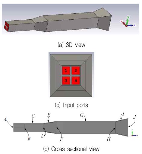
Fig. 1 shows the structure of the proposed monopulse feed horn. The feed is of multi-mode single aperture type. Since the feed operates in dual-polarized mode, the structure should be symmetric in both horizontal and vertical directions. The horizontally-polarized gain patterns are simply those of vertical polarization rotated by 90 degrees. The proposed structure is new and has not been fully presented by any other researchers in the open literature.
The designed feed consists of the following parts: an input section(A), mode-generating sections(B, D, F, H), phasing sections(C, G), aperture expansion sections (E, I) and a radiating aperture(J). Fig. 1(b) shows input ports consisting of four square waveguides. For vertical and horizontal polarizations, the ports are excited with the y-polarized TE10 and x-polarized TE01 modes, respectively.
Required monopulse patterns consist of a sum pattern(Σ), an azimuth difference pattern(ΔH), and an elevation difference pattern(ΔV). For a sum pattern, all four ports(E1, E2, E3, E4) are excited with a same phase. For azimuth and elevation difference patterns, a monopulse comparator or combiner generates (E2+E4)-(E1+E3) and E1+E2)-(E3+E4), respectively. To generate monopulse patterns from a single aperture, the horn needs to be excited with a proper combination of waveguide modes for each of three patterns(Σ, ΔH, ΔV). The TE-mode electric field inside a rectangular waveguide with broad wall width a and narrow wall width b is given by
| (1a) |
| (1b) |
Half-sine type aperture distributions for the sum pattern in x and in y directions are given by
| (2) |
corresponding to mode numbers m = 1 and n = 0, 2 respectively. Full-sine type aperture distributions for the difference pattern in x and in y directions are given by
| (3) |
corresponding to mode numbers m = 2 and n = 1, 3 respectively. Cross-polarization components(with electric field in x direction) are present when n is greater thant zero. Auxiliary higher-order modes are added to the aperture field in order to modify the edge taper level and the taper shape of the half-sine and full-sine distributions for better pattern symmetry and thus lower cross polarization. Table 1 summarizes the modes used for the sum, azimuth and elevation difference patterns.
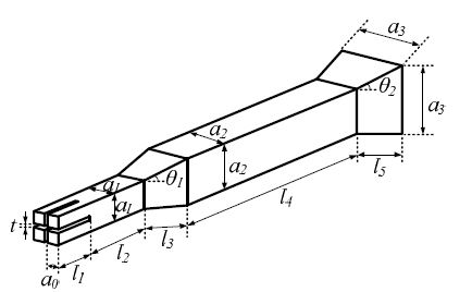
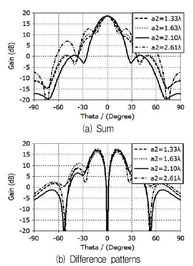
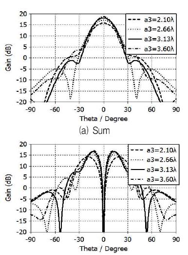
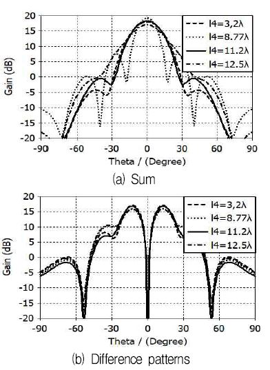
Fig. 2 shows the dimensional parameters of the proposed monopulse feed. The design of a dualpolarized multi-mode monopulse feed requires laborious adjustments of dimensional parameters. Based on the design concept [9]-[11], an optimum design of the proposed feed is obtained by extensive parametric analysis and repetitive adjustments of dimensional parameters. Most critical dimensions are a2, a3, and l4. The parameters a2 and a3 control the magnitude of higher-order modes generated in the flared discontinuities D and H in Fig. 1. The parameter l4 determines the relative phases of the fundamental and higher-order modes.
Fig. 3 shows the gain patterns versus the parameter a2. Gain patterns are sensitive to a2 whose optimum value is found to be 2.10 wavelengths. A similar dependence on parameters a3 and l4 can be observed in Figs. 4 and 5, where optimum values are 3.13 and 11.2 wavelengths, respectively.
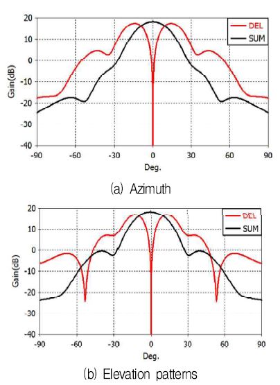
Repeated adjustments of dimensional parameters give a final optimum design of the proposed multi-mode monopulse feed whose gain patterns are shown in Fig. 6.
The sum pattern has maximum gain of 18.2dBi, gain taper of 11.6dB and 12.4dB at 22.3° in the Hand E-plane directions respectively, and side-lobe levels of -20.5dB and -19.1dB in the H- and E-plane directions respectively.
The azimuth difference pattern has maximum gain of 17.4dBi, gain taper of 2.8dB at 22.3° and side-lobe level of -12.9dB. The elevation difference pattern has maximum gain of 16.8dBi, gain taper of 4.4dB at 22.3°, and side-lobe level of -9.5dB. The difference patterns have null depths greater than 50dB.
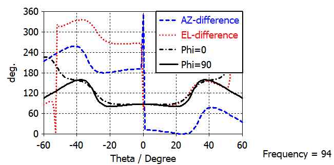
Fig. 7 shows the phase patterns of the designed feed. The phase center is just at the aperture of the feed. It is important that all three monopulse patterns have a common phase center. The designed feed has a desirable phase pattern characteristics as can be seen in Fig. 7. The sum and elevation difference patterns have an almost constant phase over ±22.3°, while the azimuth difference pattern has ±6.5° phase deviation.
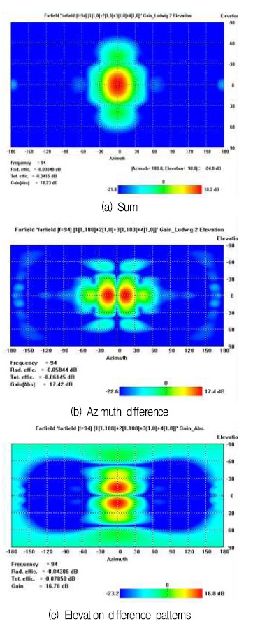
Fig. 8 shows the two dimensional gain patterns of the designed feed. The sum pattern of Fig. 8(a) shows a good pattern symmetry with low levels of wide angle side-lobes. The azimuth difference pattern (H-plane pattern) of Fig. 8(b) shows better side-lobe performance than the elevation pattern of Fig. 8(c) (E-plane pattern) as expected.
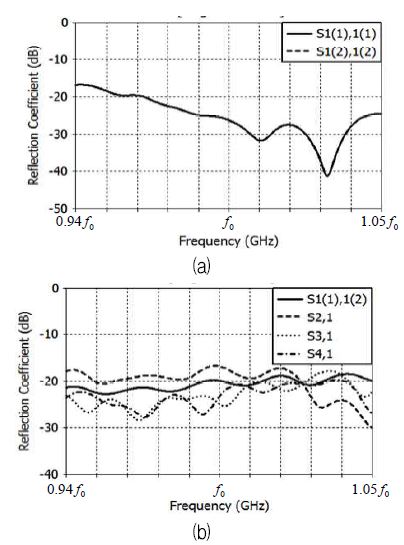
Fig. 9(a) shows input reflection coefficient of the designed feed. Due to the structural symmetry, all of the four input ports have the same reflection coefficient. Fig. 9(b) shows the polarization and port-to-port isolation characteristics of the designed feed. S1(1),1(2) refers to the isolation between vertical and horizontal polarizations at port 1. The polarization isolation is better than 18dB. S2,1 to S4,1 refer to the isolation between port 1 and port 2 to port 4. The port-to-port isolation is better than 16dB. These levels of polarization and port isolation are not insignificant considering the fact that four input waveguides are closely put together and radiate into a common small horn.
Ⅲ. Monopulse Seeker Antenna Design
The designed feed is applied to a Cassegrain reflector antenna whose main-reflector diameter, focal length and sub-reflector diameter are 50, 30 9.2 wavelengths, respectively.
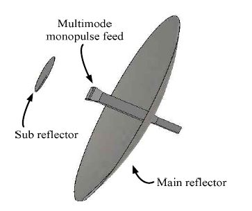
Fig. 10 shows the structure of the designed reflector antenna. For full-scale developments, feed and sub-reflector support structures and a radome have to be added. The aperture diameter of the designed feed is small enough not to increase the aperture blockage more than the sub-reflector does.
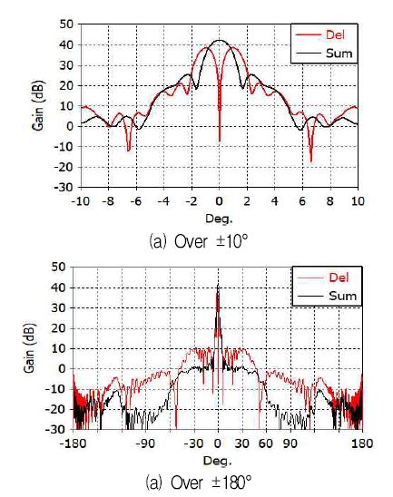
Fig. 11 shows the azimuth gain patterns of the designed seeker antenna. The gain patterns have been calculated by illuminating the combined structure of the sub-reflector and main reflector with the far-field patterns of the designed feed. This is an approximation since the interaction(i.e., multiple scattering) of the feed with the reflector system is not included.
The sum pattern has maximum gain of 42.2dBi (68% aperture efficiency), beamwidth of 1.41°, sidelobe level of -16.8dB, and far-out side-lobe levels of less than -35dB. The difference pattern has maximum gain of 38.6dBi, gain cross-over angle of 1.61° (the angle where the sum gain is equal to the difference gain), and null depth of 49.7dB relative the sum gain maximum, side-lobe level of -17.7dB, and far-out side-lobe levels of less than -28dB.
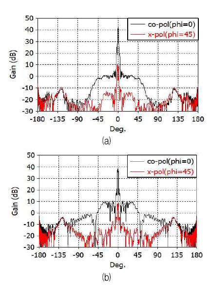
Fig. 12 shows the cross polarization gain pattern at the diagonal plane (45° plane) drawn together with the co-polarized gain patterns in the H-plane. The maximum level of the cross polarization is -32dB and -27dB in sum and azimuth difference patterns, respectively, occurring around the antenna's boresight.
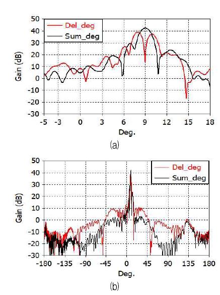
Fig. 13 shows the beam scanning characteristics of the designed seeker antenna. The main beam is scanned 9° in azimuth by rotating only the main reflector around its paraboloid vertex by 6.0°. The side-lobes are increased to -12dB level in the both sum and difference patterns. The difference pattern null depth relative the sum gain maximum is increased to 29dB. The maximum gain, the 3dB beamwidth, and the far-out side-lobe levels show negligible change.
Ⅳ. Conclusions
A W-band seeker antenna has been designed employing a Cassegrain reflector. The reflector is fed by a dual-polarized multimode monopulse horn with four square waveguides at its input. The feed horn has been optimally designed based on extensive parametric analysis. The designed feed shows good monopulse patterns and the resultant reflector antenna has excellent characteristics. The designed seeker antenna has 42.2dB gain, 1.41° beamwidth, 1.61° cross-over angle, 49.7dB null depth, and -16.8B sidelobe level. The design presented in this paper can be applied to the development of a high-performance dual-polarized W-band seeker.
Acknowledgments
This work was supported by a grant-in-aid of HANWHA SYSTEMS in 2017.
References
- Wikipedia,, Brimstone (missile), https://en. wikipedia.org/wiki/Brimstone_(missile) [Accessed: Jan. 12, 2018].
- P. Mikulich, R. Dolusic, C. Profera, and L. Yorinks, "A high gain Cassegrain monopulse antenna", IEEE AP-S Int. Symp. Dig, p375-382, Sep), (1968.
-
J. M. Lee, J. W. Noh, D. H. Kim, Y. T. Choi, and B. C. Ahn, "Design of a Cassegrain reflector for monopulse antenna", Journal of KIIT, 13(11), p1-8, Nov), (2015.
[https://doi.org/10.14801/jkiit.2015.13.11.1]

-
K. M. Lee, and R. S. Chu, "Design and analysis of a multimode feed horn for a monopulse feed", IEEE Trans. Antennas Propagat, 36(2), p171-181, Feb), (1988.
[https://doi.org/10.1109/8.1094]

-
S. G. Yu, C. S. Park, S. W. Choi, J. H. Bang, and B. C. Ahn, "Design and fabrication of a Ka-band monopulse feed horn", Journal of KIIT, 13(10), p77-84, Oct), (2015.
[https://doi.org/10.14801/jkiit.2015.13.10.77]

- S. R. Jo, Y. S. Jung, D. H. Kim, C. Y. Oh, and B. C. Ahn, "Design of a dual-polarized monopulse antenna employing crossed dipoles", Journal of KIIT, 11(11), p75-82, Nov), (2013.
- P. Zheng, G. Q. Zhao, S. H. Xu, F. Yang, and H. J. Sun, "Design of a W-band full-polarization monopulse Cassegrain antenna", IEEE Antennas Wireless Propagat. Lett, 16, p99-103, Apr), (2016.
-
K. J. Lee, C. H. Jung, J. G. Baek, C. H. Park, and S. Nam, "Design of dual-polarized monopulse Cassegrain antenna for W-band millimeter-wave seeker", Journal of KIEES, 27(3), p261-268, Mar), (2016.
[https://doi.org/10.5515/kjkiees.2016.27.3.261]

- S. B. Cohn, "Multimode horn antenna", U.S. Patent, 3,662,393, (1972).
- R. Chun, Z. Ding, K. R. Kim, O. Sodnomtseren, and B. C. Ahn, "Modal analysis of a singleaperture monopulse feed horn", Journal of KIIT, 6(6), p187-194, Jun), (2008.
- R. J. Liu, and W. B. Dou, "Design and analysis of 3mm multimode monopulse feed", Proc. Int. Conf. Microw. Millimeter Wave Tech, p1-3, 18-21, Apr), (2007.

2016. 2 : BS, Information and Communication Eng., Chungbuk National University
2016 ~ Present : MS, Radio and Communications Eng., Chungbuk National University
Research interests : Antennas

2016. 9 : MS, Information and Communication Eng., Chungbuk National University
2016 ~ Present : MS, Radio and Communications Eng., Chungbuk National University
Research interests : Antennas

1992. 12 : Ph. D., Electrical Eng., University of Mississippi.
1992 ~ 1994 : Researcher, Agency for Defense Development
1995 ~ Present : Professor, Radio and Communications Eng., Chungbuk National University
Research interests : Antennas, applied EM

2009. 2 : BS, Electronics, Ajou University
2016. 2 : Ph. D., Electronics, Ajou University
2016. 3 ~ 2016. 9 : Researcher, Hanwha-Thales
2016. 9 ~ Presnet : Researcher, Hanwha Systems
Research interests: Antennas and propagation, radome electromagnetic analysis

1997. 2 : BS, Radio Eng., Chungbuk National University
1999. 2 : MS, Radio Eng., Chungbuk National University
2003. 8 : PhD, Radio Eng., Chungbuk National University
2003. 9 ~ 2008. 2 : Associate Researcher, Kukdong Communications Co.
2008. 3 ~ 2009. 6 : Research Professor, KAIST
2009. 7 ~ 20016. 1 : Research Professor, Chungbuk National University
2016. 2 ~ Present : Principal Researcher, Duta Technology Co.
Research interests: Computational electromagnetics, near-field antenna measurements, antennas

