Implementation of Broadband and Wide Angle Array Antenna
Abstract
The novel microstrip patch antenna with broadband and wide angle has been proposed by a new type of possibility, and implemented for short range radar applications and industrial sensors. Target detection ambiguity issue as well as blind spot is still the main problem in a short-range radar and an ultra-short-range radar. In this paper, an array antenna including the new type radiators for a short-range radar that satisfies over the 77~81 GHz frequency band has been designed and fabricated, and has a wide beam width of 150 degrees or more. The antenna operating at the 79GHz band has the 4 GHz bandwidth from 77 GHz to 81GHz for enabling precise target detection. The radar system including this antenna is mounted on the corner or side of vehicle and has a precise target detection function for blind spots. The highlights of proposed array antenna are high gain of 12dBi, broad bandwidth of 4 GHz, wide angle of target detection in 160 degrees, low complexity and low cost.
초록
광대역 및 광각을 가진 새로운 마이크로스트립 패치 안테나는 새로운 유형의 가능성에 의해 제안되었으며 단거리 레이더 애플리케이션 및 산업용 센서를 위하여 구현되었다. 단거리 레이더와 초단거리 레이더에서는 표적 탐지 모호성 문제와 사각지대가 여전히 주요한 문제이다. 본 논문에서는 77-81GHz 주파수 대역을 만족하는 신형 단거리 레이더용 방사체를 포함하는 어레이 안테나를 설계 및 제작하였으며, 150도 이상의 넓은 빔폭을 갖는다. 79GHz 대역에서 동작하는 안테나는 77GHz ~ 81GHz의 4GHz 대역폭을 가지고 있어 정확한 표적 탐지가 가능하다. 이 안테나를 포함하는 레이더 시스템은 차량의 모서리나 측면에 장착되어 사각지대에 대한 정밀한 표적 탐지 기능을 가지고 있다. 제안된 어레이 안테나의 주요 특징은 12dBi의 높은 이득, 4GHz의 넓은 대역폭, 160도의 넓은 표적 탐지 각도, 낮은 복잡성 및 저렴한 비용이다.
Keywords:
novel microstrip patch antenna, broad bandwidth, wide angle, short range radar, target detectionⅠ. Introduction
Array antennas applicable to short-range radar(SRR) among vehicle radars must be designed in a millimeter band of 24 GHz or 79 GHz. In particular, an ultra-short-range radar(USRR) for blind spot detection (BSD) does not cause object non-recognition problem when using array antennas with beam widths greater than 150 degrees in the 77-81 GHz band. The detectable range of the radar is indicated by the field of view(FoV), and the horizontal width of the FoV has the greatest effect on the 3 dB beam width of the antenna[1]-[3].
In general, conventional microstrip patch antennas meet only a bandwidth of about 2 to 2.5 GHz at W-band and a coverage of 100 degrees[4][5], but the antenna of the wide angle radar requires a 4 GHz bandwidth of 77-81 GHz and a coverage of 150 degrees. An antenna structure that can be easily implemented in the millimeter wave band is a microstrip patch antenna using a printed circuit board(PCB). It is also possible to implement antennas of different structures such as a coplanar waveguide antenna, but most of them use microstrip patch antennas when considering connections with other systems. Microstrip patch antennas have an operating frequency bandwidth of less than 3% when using only a single patch. And usually the beam width is about 100 degrees. Its E-plane pattern and H-plane pattern have different beam widths, and E-plane pattern beam width is wider.
In this paper, we design and implement an array antenna using microstrip substrate for short-range radar that covers over the 77-81 GHz band width and has a wide beam width of 150 degrees or more. Radars operating at the 79 GHz band have 4 GHz(77-81 GHz) frequency bandwidth, which has a wider bandwidth than the 200 MHz at the 24 GHz band, enabling precise detection. This radar is mounted on the corner or side of vehicle and has a precise target detection function for blind spots.
Ⅱ. Antenna Element Configuration
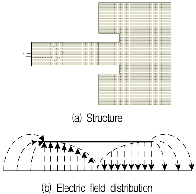
Fig. 1 shows a typical microstrip patch antenna structure and the electric field distribution of the patch. Microstrip antennas consist of a very thin metallic strip(Patch) placed a small fraction of a wavelength above a ground plane. Rectangular microstrip patch antennas are half-wavelength structures and are operated at the fundamental resonant mode of TMZ modes[6][7]. The fundamental TM10 mode implies that the field varies one l/2 cycle along the length, and there is no variation along the width of the patch. It may be observed from Fig. 1(a) that the vertical components of the electric field at the two edges along the width are in opposite directions and hence cancel one another in the broadside direction, whereas the horizontal components are in same direction and hence combine in the broadside direction. Therefore, the edges along the width are termed as radiating edges[8]-[12].
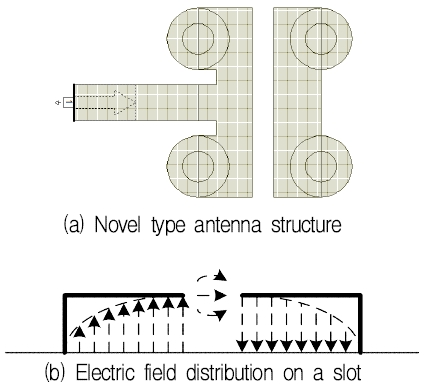
Fig. 2 shows the structure for microstrip patch antenna proposed in the paper. The bottom surface of the PCB board is used as a ground plane, and the top surface consists of two radiators. One of the radiators is connected directly to the feeder line, and the other is electromagnetically coupled through a separate slot between the two opposing radiators and acts as a parasitic radiator.
In a conventional rectangular patch antenna, the longitudinal ends of the patch with half-wavelength are open, so the electric field distribution is strong in both longitudinal cross sections of the ends. However, in the proposed antenna structure, both corner ends are shorted to the ground through via hole, and the center of patch is cut to be a transverse slot, so that the electric field is distributed most strongly in the slot. The direct-fed radiator is the main radiator and plays a major role in radiating radio waves from the antenna. The parasitic radiator, which is electromagnetically coupled through the main radiator, has another resonant frequency due to a different size and widens the bandwidth of the antenna. In addition, by placing the slot parallel to the ground plane, it operates similarly to a waveguide slot antenna or a magnetic dipole antenna. Also, by adjusting the width of the slot, the beam width of the antenna can be widened or narrowed.
The proposed antenna is designed on the dielectric substrate RO3003 with a thickness of 5 mil(er=3.0, tand=0.001) and the dimension of the designed antenna is summarized in Table 1. The proposed antenna is designed by AWR AXIEM at Cadence.
Fig. 3 shows the impedance characteristic variation by sweeping of the design parameters. The lengths of two patches control the resonant frequency of the designed radiator. However, the ratio between the lengths of two patches is very important for impedance matching.
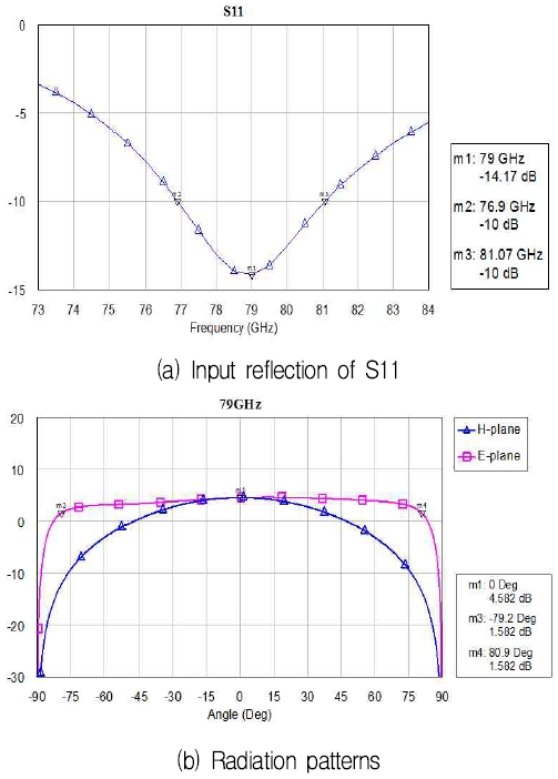
Fig. 4 shows the simulated results of the proposed antenna. The 10 dB bandwidth of the designed antenna is 76.9 to 81.07 GHz as shown in Fig. 4(a). The antenna has the enough impedance bandwidth for an ultra-short range radar operated in 77-81 GHz bandwidth[13]. Fig. 4(b) shows the radiation patterns of the designed antenna. The antenna has the peak gain of 4.582 dBi and the 3 dB beamwidth of 160.2 deg at E-plane pattern.
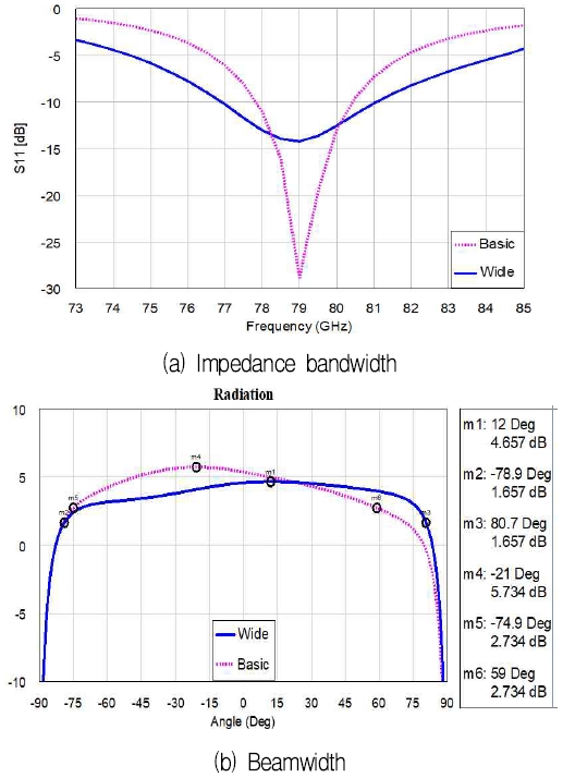
Fig. 5 compares the designed results of two antenna structure of shown in Fig. 1 and Fig. 2. The general microstrip antenna of Fig. 1 have the 10 dB impedance bandwidth of 2.3 GHz, the peak gain of 5.734 dBi, and the 3 dB beamwidth of 133.9 deg. The proposed antenna of Fig. 2 has the characteristics of 4 GHz 10 dB impedance bandwidth, 4.657 dBi peak gain, and 159.6 deg 3 dB beamwidth. The proposed antenna have wider 10 dB impedance bandwidth and 3 dB beamwidth than the general antenna.
Ⅲ. Array Antenna Design
An array antenna composed of with novel type patches on a microstrip substrate is shown in Fig. 6. The geometry of the array antenna consists of a center feeding that is fed between the fifth and sixth radiating elements, which are central positions, and is symmetrically arranged with respect to each other based on a midpoint. With this configuration, the H-plane radiation pattern in the array axis direction can be designed to have symmetry, and the maximum gain can be obtained at zero degrees. The amplitudes of the signals supplied to the radiating elements are designed to have a 26 dB side-love level by applying the array principle to the Chebyshev polynomial[6], and the phases of the signals supplied to each radiating element are all the same or a multiple of 2 radian.
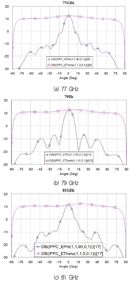
The E-plane and H-plane radiation pattern shown in Fig. 7 are the results for determining the direction of maximum gain in both planes and wide angle condition. The maximum gain is 12.5 dBi and half-power beam width is 152.5 degrees with wide-angle in the H-plane. In the case of recent wide-angle radar, FoV is determined based on the 10 dB beam width rather than the 3 dB beam width. If the beam width of the antenna is defined in this condition, the beam width of the antenna is 160 degree or more. In addition, the E-plane radiation pattern has a very narrow half-power beam width of about 9.5 degrees and maximum gain is 12.41 dBi. The side-lobe level has been designed at 26 dB, but reduced to the 20 dB due to phase error and loss due to the feeder line to supply the RF signals into the array patch antenna. The radiation patterns of the designed array antenna are summarized in Table 2.
Ⅳ. Antenna Fabrication and Measurement
In order to analyze the characteristics of the antenna, the dielectric substrate used in design and fabrication is RO3003 with a thickness of 5 mil(er=3.0, tand=0.001). In the millimeter wave band of 79 GHz, it is very difficult to measure the PCB antenna using the microwave band connectors. Hence, for the connection between the antenna and the measurement system, the transition is desired to connect the waveguide and the microstrip antenna. The biggest problem in this measurement method is that the PCB substrate used for development is very thin, and the difficulty of the processing is very high, so even if there is a slight processing error in the connection, accurate antenna measurement is impossible.
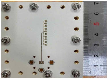
Fig. 8 shows the fabricated array antenna. The antenna has the microstrip to waveguide transition and is fixed on the flange to connect standard WR-10 waveguide of the measurement system.
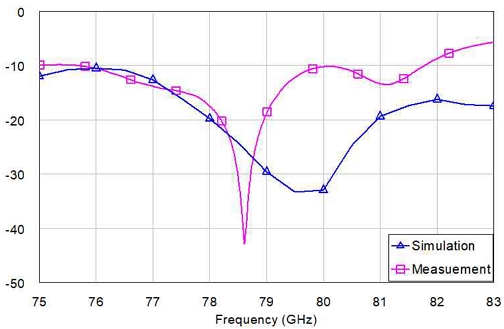
Analyzing the results shown in the Fig. 9, the measured resonant frequency appears similar to the simulation result, but it can be seen that the resonance trends differ from each other. The reason is believed to be caused by the aforementioned causes. From the result, the antenna bandwidth is in the range of the 76 GHz to 81.75 GHz based on -10 dB (VSWR<2) and has a wideband characteristic.
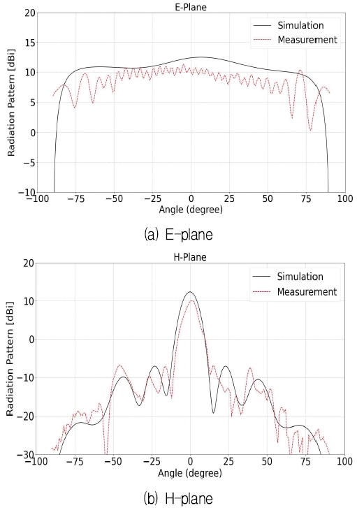
Fig. 10(a) shows E-plane radiation patterns compared the simulation results with the measured results. The maximum gains of the antenna operating at 79 GHz are obtained 12.4 dBi at 0 degrees and 9.9 dBi at 1 degrees.
The half-power beam width of the antenna has a narrow beam width in 4 degrees and 3 degrees, respectively. Fig. 10(b) shows H-plane radiation pattern with flat gain. The flat gains are obtained 12.5 ± 3 dBi and 10.75 ± 3 dBi in the range from -80 degree to 80 degree, respectively. The measured pattern slightly vibrates when compared with the simulation pattern because of the measurement by summing the direct wave and the reflected wave inside imperfect anechoic chamber.
Ⅴ. Conclusion
This novel antenna structure has been proposed in this paper for broadband and wide angle detection because of its advantages such as low power handling, low manufacturing cost, simplicity and good performance in millimeter wave application. Furthermore, array antenna applicable to short range radar among vehicle radars has been designed and fabricated in the millimeter band of 79 GHz. The measurement results show that the proposed antenna structure provides an improvement in the characteristics of broad bandwidth and wide angle view compared to conventional microstrip patch antenna. Moreover, the measurement results have shown the flat gain of 12dBi, view angle of 160 degrees and the bandwidth of 4GHz from 77 GHz to 81 GHz, and agreed well with simulation results.
Acknowledgments
This work was supported by the 2022 scientific promotion program funded by Jeju National University
References
- Yole Development, "Automotive industry: radar is part of the ADAS, autonomous driving revolution", Microwave Journal E-book, pp. 11-12, Dec. 2017.
-
K. Ramasubramanian, K. Ramaiah, and A. Aginskiy, "Moving from legacy 24 GHz to state-of-the-art 77 GHz radar", Texas Instruments, pp. 46-49, May 2018.
[https://doi.org/10.1007/s38314-018-0029-6]

- C. Iovescu and S. Rao, "The fundamentals of millimeter wave sensors", Texas Instruments, May 2017.
-
S. Yoo, Y. Milyakh, H. Kim, C. Hong, and H. Choo, "Patch array antenna using a dual coupled feeding structure for 79 GHz automotive radar applications", IEEE Antennas and Wireless Propagation Letters, Vol. 19, No. 4, pp. 676-679, Apr. 2020.
[https://doi.org/10.1109/lawp.2020.2976545]

-
G. Su, E. Li, T. Kuo, H. Jin, Y. Chang, and K. Chin, "79-GHz wide-beam microstrip patch antenna and antenna array for millimeter-wave applications", IEEE Access, Vol. 8, pp. 200823-200833, Nov. 2020.
[https://doi.org/10.1109/access.2020.3035750]

-
K. R. Carver and J. W. Mink, "Microstrip Antenna Technology", IEEE Transactions on Antennas and Propagation, Vol. 29, No. 1, pp. 2-24, Jan. 1981.
[https://doi.org/10.1109/TAP.1981.1142523]

- K. C. Gupta and A. Benalla, "Microstrip Antenna Design", Artech House, pp. 384, 1988.
- C. A. Balanis, "Antenna Theory: Analysis and Design", 3rd, John Wiley & Sons, Inc., 2005.
- G. Kumar and K. P. Ray, "Broadband Microstrip Antennas", Artech House, 2003.
-
Z. N. Chen and M. Y. W. Chia, "Broadband Planar Antennas", John Wiley & Sons, 2006.
[https://doi.org/10.1002/0470871768]

-
S. Palanivel Rajan and C. Vivek, "Analysis and Design of Microstrip Patch Antenna for Radar Communication", Journal of Electrical Engineering & Technology, Vol. 14, pp. 923-929, 2019.
[https://doi.org/10.1007/s42835-018-00072-y]

-
D. H. Park, "Analysis and design of dual-band microstrip array antenna for automotive radar", Journal of KIIT, Vol. 14, No. 7, Jul. 2016.
[https://doi.org/10.14801/jkiit.2016.14.7.53]

- J. Singh, B. Ginsburg, S. Rao, and K. Ramasubramanian, "AWR1642 mmWave sensor: 76-81 GHz radar-on-chip for short-range radar applications", Texas Instruments, May 2017.

1995 : BS degree in Department of Telecommunication Engineering, Jeju National University.
1997 : MS degree in Department of Telecommunication Engineering, Jeju National University
Research interests : RF and Microwave, antennas, automotive radar, mm-wave systems

2000 : BS degree in Department of Telecommunication Engineering, Jeju National University.
2002 : MS degree in Department of Electrical and Comupter Engineering, Hanyang University
2007 : PhD degrees in Department of Electrical and Comupter Engineering, Hanyang University
Research interests : antennas, automotive radar, mm-wave systems and metamaterials

1984 : BS degree in Department of Telecommunication Enginnering, Jeju National University
1989 : MS degree in Department of Electronic Telecommunication Enginnering, Hanyang University
1992 : PhD degrees in Department of Electronic Telecommunication Enginnering, Hanyang University
1992 ~ present : Professor in Department of Telecommunication Enginnering, Jeju National University
Research interests : RF and wireless communication systems, antenna and microwave systems

